Zhejiang ZUCH Technology Co., Ltd.
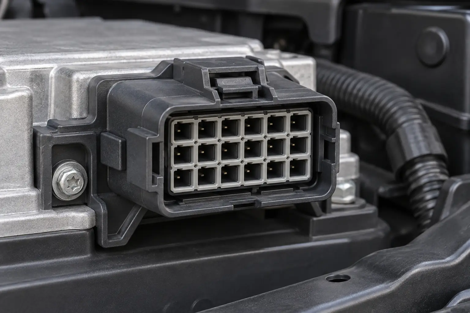
When a systems engineer in Osaka bought a visually similar 24-position connector for a control-unit harness, the sample appeared to mate but immediately failed the bench build: the keying resisted full engagement, the seal geometry did not close, and the pinout no longer matched the drawing. The connector was not simply defective. Rework began because purchasing had been given a cavity count and photographs instead of a controlled interface specification.
Summary: Select a 24 pin automotive connector by controlling the complete interface—not by matching the 24 cavities alone. Confirm the housing family and mating half, polarization, cavity map, terminal system, wire range, seal package, latch, and validation requirements. USCAR-2 and ISO 8092 address automotive connector-system performance, while IEC 61984 has a broader connector-safety scope; none makes a visually similar housing interchangeable. Freeze an interface-control drawing and inspect samples before releasing volume orders.
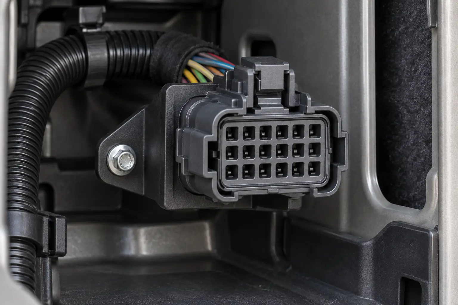
A 24-position connector is commonly used where one compact interface must carry multiple sensor, actuator, communication, ground, and low-current power circuits between a wiring harness and an electronic control unit (ECU), body controller, junction module, lighting controller, seat module, or industrial vehicle subsystem. The cavity count describes packaging capacity. It does not define current rating, voltage, pitch, terminal plating, environmental sealing, or circuit assignment. For a useful starting taxonomy, see this guide to types of automotive wire connectors.
Why Doesn’t “24-Pin” Identify a Complete or Universal Connector?
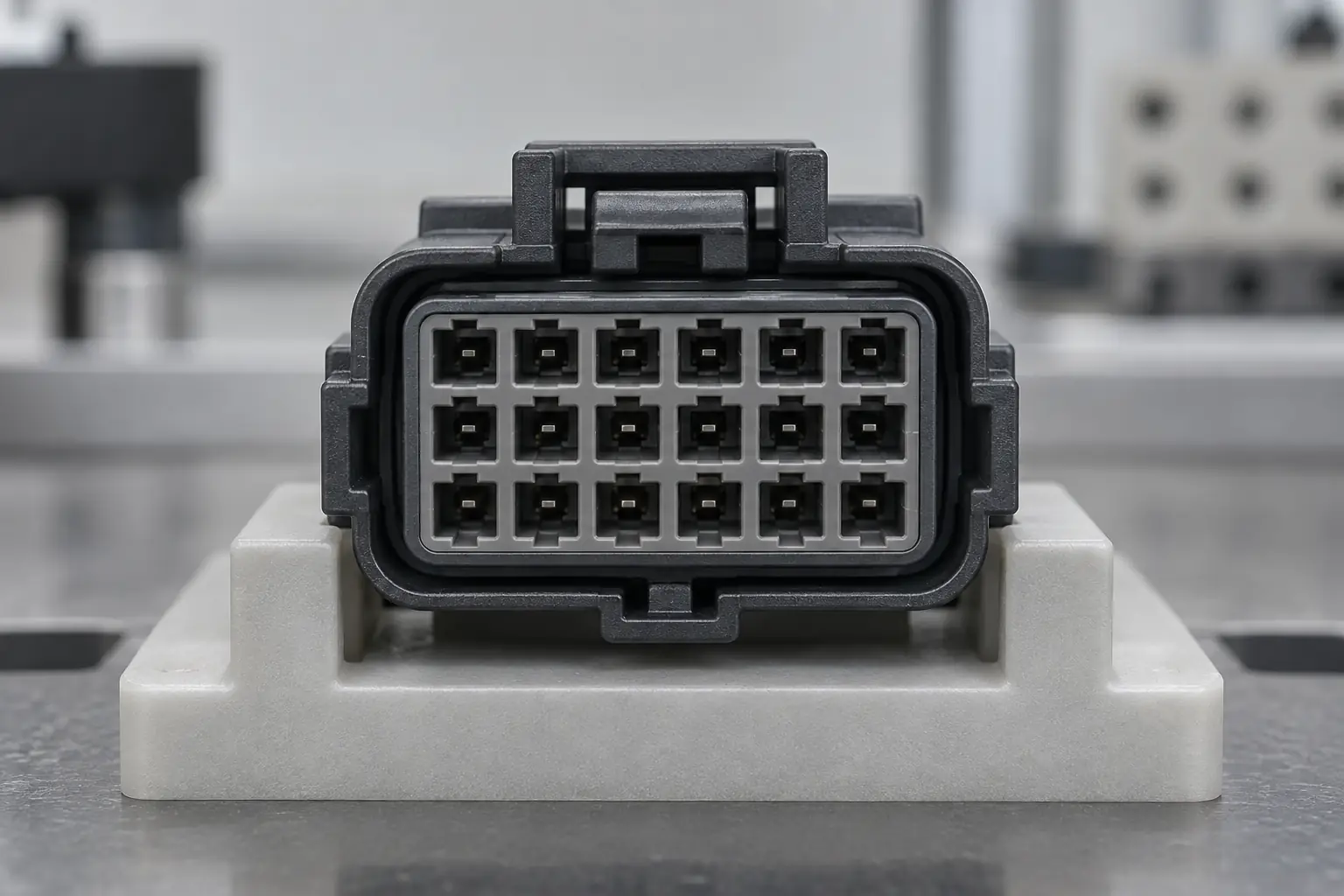
Two housings can share the same cavity count and exterior proportions yet differ at every functional interface. Key ribs, latch ramps, contact families, secondary locks, and seal profiles may all be incompatible. Even within one family, key codes can intentionally prevent cross-mating between neighboring modules.
The pinout creates a second risk. Molded cavity numbers may be read from the wire side while the harness drawing shows the mating face; mirroring the view can swap communications, sensor reference, ground, or power. Label every drawing “mating face” or “wire-entry face,” record orientation, and control intentionally empty cavities and plugs.
SAE/USCAR-2 defines electrical, mechanical, and environmental performance tests for automotive connector systems. Qualification is configuration-specific: a look-alike bare housing does not inherit the results of a tested housing, terminal, wire, seal, crimp, and mating combination.
Which Interfaces Must Be Controlled Before a 24-Pin Connector Is Approved?
How Do Keying, Latch, and Housing Features Prove the Mating Pair?
Record the family, both housing part numbers, mating-interface designation, key code, cavity arrangement, and connector-position-assurance features. “Male” and “female” can be ambiguous because a plug housing may contain female terminals. Confirm full latch engagement, secondary-lock position, and terminal retention; a low-force hand fit is not proof of compatibility.
What Seal Package Matches the Actual Installation Environment?
A sealed interface depends on coordinated elements: an interface seal, individual wire seals or a mat seal, plugs for unused cavities, and suitable rear geometry. Choose by location and duty cycle. Engine-bay, chassis, agricultural, or off-highway service may add water, dust, fluids, vibration, and thermal cycling. Ask for the applicable validation report rather than inferring an IP rating from visible rubber.
How Should the Pinout, Terminals, and Wire Range Be Matched?
Build a cavity table with circuit name, maximum continuous and transient current, wire size, insulation diameter, terminal and seal part numbers, and empty-cavity plugs. Automotive catalogs commonly span roughly 0.35–2.5 mm² (22–14 AWG), but one housing may support a narrow subset or mixed signal and power contacts. Follow the terminal application specification for strip length, crimp height, insulation support, pull-force checks, and tooling.
| Selection basis | What it controls | Likely risk | Total-cost effect |
|---|---|---|---|
| 24 cavities and photograph only | Approximate appearance | Key, seal, terminal, or pinout mismatch | Low quotation effort; high rework and return exposure |
| Housing part number only | Main molded component | Wrong mating half, terminals, seals, or accessories | Moderate risk of incomplete kits |
| Controlled connector bill of materials | Housing, counterpart, terminals, seals, locks, plugs | Process variation remains | Lower purchasing and assembly ambiguity |
| Interface drawing plus validated samples | Mechanical, electrical, environmental, and process fit | Requires more up-front engineering | Usually lowest rework and launch risk |
How Do You Turn Application Requirements Into a Procurement-Ready Package?
The hidden cost includes line stoppage, depinning labor, scrapped seals and terminals, containment, and delayed testing. Illustratively, if 200 harnesses require 12 minutes of rework, the direct burden is already 40 labor-hours before engineering review or retesting.
Use the following matrix to convert application language into evidence a supplier can answer. Test names and acceptance limits must come from the customer specification, chosen connector standard, or manufacturer validation document; they should not be invented during quotation.
| Dimension | Record before purchase | Sample or document check |
|---|---|---|
| Mechanical interface | Mating housing, key code, latch, CPA/secondary lock, envelope | Mate/unmate trial, retention check, dimensional comparison |
| Electrical interface | Pinout, current by circuit, voltage, resistance limit | 100% continuity map; voltage-drop or contact-resistance method |
| Wire termination | Wire size, strand construction, insulation diameter, plating | Crimp cross-section, crimp-height measurement, pull test |
| Environment | Mounting zone, temperature profile, fluids, vibration, ingress need | Applicable thermal, vibration, fluid, and sealing tests |
| Service | Depinning method, replacement terminals, plugs, repair limits | Authorized repair trial and post-repair continuity check |
What Do Failure Symptoms Reveal in a 24-Position Interface?
The label “24-pin” alone does not identify a universal connector or pinout, so diagnose against the vehicle schematic, connector drawing, and approved service procedure. Isolate power and follow the vehicle or equipment maker’s shutdown instructions before disconnecting or inspecting the interface; do not probe energized circuits or force test probes into terminals.
- Several circuits become intermittent together: suspect incomplete mating, a latch or connector-position-assurance (CPA) device that is not fully set, a shared power or ground path, contamination, or harness movement at the connector. With the system de-energized, verify housing engagement and CPA position visually, inspect common cavities, and compare point-to-point continuity with the controlled circuit map and approved test adapters.
- One circuit is dead: a backed-out terminal, bent contact, damaged crimp, or conductor fault is more plausible than a housing-wide failure. Confirm the cavity from the correct viewing face, inspect terminal alignment and wire-entry depth under good lighting, perform the specified retention check, and test continuity end to end without spreading the contact.
- The connector will not fully seat: stop rather than increasing force. Check the key code, terminal position assurance (TPA) or secondary-lock state, terminal back-out, bent contacts, displaced interface seals, wire-seal position, and debris; correct the identified condition under the component or repair instruction before remating.
- Moisture, residue, or corrosion is visible: document where it entered, then inspect interface seals, individual wire seals or mat seals, cavity plugs, and housing damage. Follow the manufacturer’s cleaning or replacement procedure; generic chemicals or abrasion can damage plating and elastomers.
- The fault returns after repair or vehicle motion: inspect clip placement, bend radius, service loop, pull at the rear seal, and unsupported harness mass. Restore strain relief and routing before retest because repeated relative motion can promote fretting at the contact interface; validate the repaired circuit by the approved continuity or contact-resistance method and acceptance limit.
Which Standards Apply—and What Do They Not Prove?
- SAE/USCAR-2 is a performance specification for automotive electrical connector systems. It provides a structured basis for mechanical, electrical, and environmental testing, but it is not a universal certificate for every configuration sold under a family name.
- ISO 8092 is a series covering connections for on-board road-vehicle electrical wiring harnesses, including terminology, dimensions, test methods, and performance requirements by part. The exact part and edition must match the connection type and customer program.
- IEC 61984 covers safety requirements and tests for connectors within its stated scope. It is broader than automotive harness validation and does not replace vehicle-specific vibration, fluid, temperature, sealing, or OEM requirements.
These documents define test frameworks and requirements; they do not prove that an unverified catalog item is “certified.” Commercially, unsupported compliance language can cause rejected PPAP or customer submissions, warranty disputes, and avoidable retesting. State the standard, part, edition, test configuration, laboratory, and result. Also confirm destination-market rules and customer specifications, which can be stricter than a general standard.
Which Five Steps Reduce Selection and Repair Risk?
- Identify the installed interface. Record molded markings, connector views, cavity numbering, wire colors, dimensions, key position, and module/header details. This connector identification guide shows what evidence to collect.
- Freeze the connector bill of materials. List both housings, terminals by wire range and plating, seals, cavity plugs, secondary locks, backshells, clips, and approved tooling.
- Audit the pinout. Compare the ECU drawing, harness drawing, and sample from the same viewing direction; then perform point-to-point continuity testing before power is applied.
- Build and inspect samples. Follow controlled crimp settings and record objective measurements. See how to crimp automotive connectors for the process fundamentals.
- Approve repairs before production. Define whether individual terminals may be replaced, the permitted depinning tool and number of rework cycles, and the post-repair inspection and electrical test. Review this automotive connector depinning guide before attempting extraction.
For buyers comparing a 24 pin automotive connector, ZUCH can support the sourcing conversation with configurable connector and terminal options and application-oriented documentation. Final suitability should still be confirmed against the buyer’s controlled interface, wire specification, validation plan, and mating component.
Frequently Asked Questions
What is a 24-pin automotive connector typically used for in multi-circuit control units and harnesses?
It is commonly used to consolidate multiple sensor, actuator, communication, ground, and power circuits at an ECU, body controller, lighting module, seat system, junction unit, or similar subsystem. The 24 positions describe circuit capacity, not the electrical load each cavity can carry, so the pinout and terminal family must be engineered per circuit.
How do I confirm that a 24-pin automotive connector matches my vehicle wiring?
Match the complete housing part number and key code, mating counterpart, cavity numbering view, pinout, terminal series, wire size and insulation diameter, sealing components, and latch or secondary lock. Then compare a sample with the drawing and run point-to-point continuity testing before applying power.
Do 24-pin automotive connectors need a matching male and female housing?
They need a specified mating interface, which may be two cable housings or a cable housing and PCB/module header. Do not source by “male” and “female” alone; identify the exact housing and contact-gender combination because terminology varies across suppliers.
What terminal and wire-gauge options are common for a 24-pin automotive connector?
Many automotive ranges offer signal and power contacts for wire sizes somewhere within approximately 0.35–2.5 mm² (about 22–14 AWG), but one housing may accept a much narrower range. Confirm terminal part number, plating, current derating, insulation diameter, seal range, and approved crimp specification for every circuit.
When should I choose a sealed 24-pin automotive connector?
Choose a sealed system when the mounted connector can encounter water, dust, condensation, road splash, cleaning processes, or fluids. Specify the actual exposure and validation method; a visible seal alone does not demonstrate that the assembled connector meets the required ingress or environmental performance.
Can I replace one terminal in a 24-pin connector without replacing the full housing?
Often yes, if the housing, lock, seal, and cavity are undamaged and the manufacturer or vehicle repair procedure permits terminal service. Use the correct release tool, install a new approved terminal and seal when required, restore the secondary lock, and verify retention plus continuity; replace the housing if extraction damages the cavity or latch.
Which Primary Sources Support This Selection Method?
- SAE International, USCAR-2: Performance Specification for Automotive Electrical Connector Systems
- International Organization for Standardization, ISO 8092 series: Road vehicles—connections for on-board electrical wiring harnesses
- International Electrotechnical Commission, IEC 61984: Connectors—safety requirements and tests
The durable lesson from the Osaka rework is simple: cavity count starts the search, but interface control finishes it.
To shortlist a 24 pin automotive connector and the matching housings, terminals, and sealing components, review ZUCH connector products and contact the team with your interface drawing, circuit table, wire data, environment, and expected validation requirements.