Zhejiang ZUCH Technology Co., Ltd.
Illustrative scenario only; this is not a documented customer case. When a harness engineer in Detroit moved a pilot appliance lead into a compact right-angle disconnect, several conductors pulled loose during bench handling within minutes. The team first blamed a weak terminal. The investigation instead pointed to an uncontrolled wire-terminal-tool combination: the barrel, strip length, insulation support, and applicator setup had never been validated together.
Summary: A reliable 250 flag terminal thin-wire crimping process starts with the exact terminal drawing, approved conductor and insulation range, and dedicated application tooling. “250” commonly refers to the nominal 0.250 in (6.35 mm) tab-width family; IEC 61210 uses a 6.3 mm flat quick-connect size, but neither label proves tab thickness, fit, wire range, material, plating, current rating, retention, or certification. Establish crimp height and pull-force limits from the terminal supplier’s specification and production-representative validation samples—never from a generic online value.
What does “250” identify, and what still requires a drawing?
In North American catalogs, “250” commonly means a nominal 0.250-inch tab-width family; the direct conversion is 6.35 mm. IEC 61210:2010 includes a 6.3 mm size among non-insulated flat quick-connect terminations. This naming does not make every 250 part interchangeable. The controlled drawing must still define width tolerance, tab thickness, detent, mating forces, and permitted terminal-wire combinations.
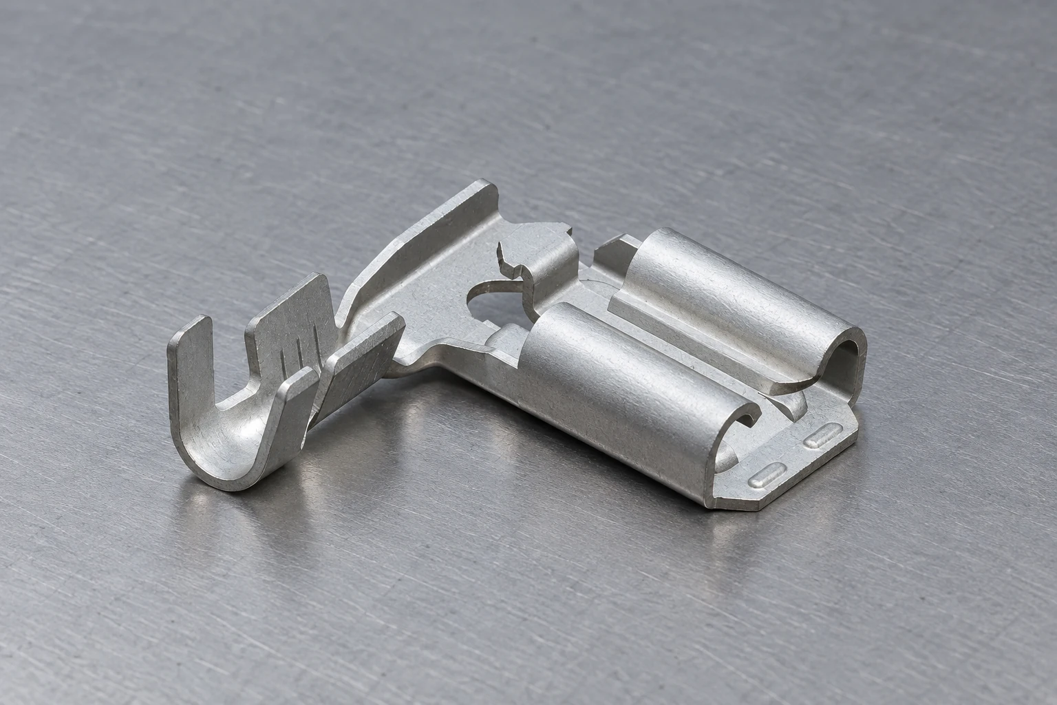
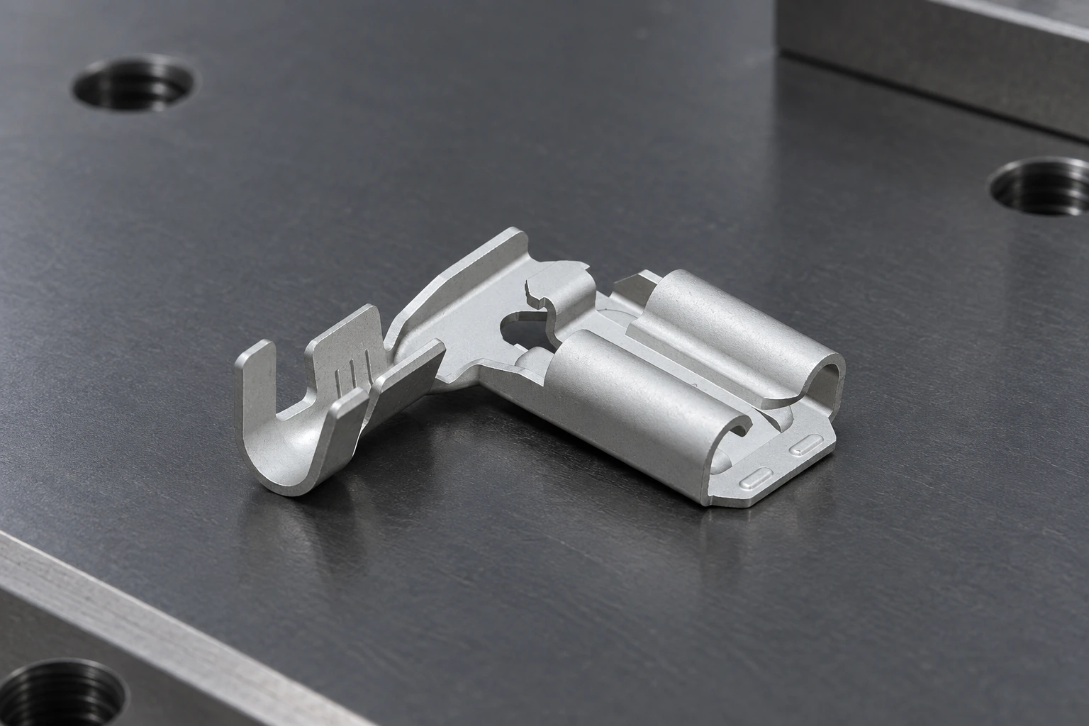
The featured image shows an uninsulated right-angle female quick-connect/flag-style terminal. It cannot establish wire range, material, plating, ratings, tab thickness, retention, certification, or application; those remain unknown without the part number, drawing, specification, and reports.
Flag geometry also changes tooling access. A die for a similar straight receptacle may not locate or form the terminal correctly; orientation, locator, wire stop, feed, and anvil/profile all belong to the controlled process.
Why does thin-wire crimping fail even when the terminal looks closed?
A thin conductor fills less of the barrel. In a barrel designed for larger wire, the wings can bottom, overlap, or form around empty space before producing the intended compression. A closed-looking barrel may therefore hide poor compaction, asymmetry, strand damage, or an unstable interface. Confirm the exact conductor construction instead of copying another terminal’s crimp height.
Stripping errors matter more on thin wire: a nick removes part of a small cross-section, excess strip exposes conductor or defeats strain relief, and insufficient strip can trap insulation in the conductor barrel. Verify wire-end position using the application specification’s inspection features.
| Termination strategy | Technical advantage | Primary risk | Release decision |
|---|---|---|---|
| Terminal approved for the thin wire | Barrel, wire, and tooling can be validated together | Requires specified applicator and setup | Preferred with documentation and representative samples |
| Larger-wire terminal without approval | May reduce part count | Unknown compression and stability | Do not release from appearance or one pull test |
| Folded conductor | Increases apparent fill | Can damage strands and change the qualified process | Use only when explicitly specified and validated |
| Approved splice or pigtail | Uses a documented interface wire | Adds a termination and inspection point | Compare lifecycle risk with a purpose-sized terminal |
How do the conductor crimp and insulation crimp perform different jobs?
The conductor crimp creates the electrical and mechanical connection to stripped strands. Its form, compression, strand position, bellmouth, and cutoff must meet the manufacturer’s criteria. The insulation crimp supports the wire behind that connection; it cannot compensate for a poor conductor crimp. When re-pinning automotive connectors, inspect both crimp zones before seating the replacement terminal. The same distinction matters when using automotive wire connectors: insulation support is not an electrical termination.
| Control point | Conductor crimp | Insulation crimp |
|---|---|---|
| Primary role | Electrical path and grip on conductor strands | Strain support around insulation |
| Input that must match | Barrel, conductor and tooling profile | Support wings, insulation OD/material and tooling |
| Typical visible concerns | Cut strands, asymmetry, misplaced wire, flash | Loose support, pierced insulation, rolled wings |
| Acceptance evidence | Specified crimp window plus destructive/electrical validation | Specified form plus harness strain checks |
Thin strands can splay during insertion into a right-angle barrel, so the workstation must control cut and strip quality, insertion direction, and terminal support.
How should engineers establish crimp height, pull force, and process limits?
Crimp height measures the formed conductor barrel and can reveal changes in setup, tooling wear, material, or wire fill. Its target and tolerance are specific to the terminal, wire, and applicator. If the supplier specification does not cover the proposed thin wire, treat the combination as unapproved until it is validated and documented.
Pull-force testing is a destructive mechanical check; it does not prove electrical resistance, environmental stability, insulation support, or tab compatibility. Derive the requirement and preparation from the applicable specification. Record insulation-support state, pull direction and rate, conditioning, failure mode, and acceptance rule.
A practical validation sequence is:
- Freeze the combination. Record terminal/revision, wire construction, insulation, strip specification, applicator/die, press, locator, and setup.
- Create a controlled range. Make representative samples across supplier-guided settings; experiments are not released limits.
- Measure and section. Check crimp height, wire position, visible form, and cross-sections where needed for compaction, symmetry, and damage.
- Verify performance. Run defined pull tests plus electrical and environmental tests required by the equipment program.
- Control production. Define setup approval, measurement checks, sampling, maintenance triggers, traceability, and reaction rules.
Strip length belongs in the same plan. Validate the production strip tool, use the supplier’s acceptance window, and confirm that the locator or wire stop places conductor and insulation correctly. Cut strands, insulation pullback, or inconsistent insertion can defeat a correct nominal setting.
Which checks isolate the cause of a weak or unstable crimp?
| Observed symptom | Likely cause to investigate | Immediate check | Corrective direction |
|---|---|---|---|
| Wire pulls out with little visible strand deformation | Wire below approved range, high crimp height, wrong die, or incomplete stroke | Verify part/wire/tool IDs, press cycle, and measured crimp height | Return to the documented combination; do not compensate by guessing a lower setting |
| Broken strands at the barrel edge | Over-compression, poor bellmouth, nicked strands, or terminal mislocation | Inspect stripped wire, cutoff/bellmouth, section, and locator position | Correct stripping and tooling alignment; revalidate the approved setup |
| Pull result passes but resistance is unstable | Insufficient or uneven strand compression, contamination, damaged strands, or test-method mismatch | Review sections and electrical results from the same controlled sample group | Use mechanical and electrical acceptance together |
| Insulation slips from the support wings | Insulation diameter outside range, wrong profile, or excessive strip length | Measure insulation OD and strip length; inspect support-wing form | Match the insulation-support range or select another terminal |
| Flag terminal twists or will not seat in the die | Tooling intended for a straight receptacle, wrong orientation, or locator interference | Compare the applicator and locator numbers with the terminal application specification | Use tooling designed and validated for that flag geometry |
| Mated connection feels loose | Wrong tab thickness, receptacle geometry, detent, damage, or repeated mating | Check both controlled drawings and insertion/withdrawal requirements | Resolve mating-interface compatibility separately from crimp quality |
What do IEC, UL, and automotive crimp references actually cover?
IEC 60352-2:2024 covers solderless crimped connections made with appropriately designed uninsulated or pre-insulated crimp barrels, including stranded conductors from 0.05 mm² to 10 mm², within its stated scope. It provides general requirements, test methods, and practical guidance; it does not supply the missing product-specific crimp height for an unidentified terminal.
IEC 61210:2010 covers non-insulated flat quick-connect terminations using defined male-tab sizes and mating female connectors, and establishes dimensional, performance, and test-program requirements within its scope. It is relevant to the interface class, but citing it does not prove that this pictured terminal conforms or carries any certification.
UL 310 addresses electrical quick-connect terminals. For a North American appliance program, confirm whether it applies through the end-product standard and verify the exact product’s current certification record and conditions of acceptability. For an automotive cable-to-terminal program, an OEM may instead require a current SAE/USCAR crimp-performance specification such as SAE/USCAR-21; use it only when the customer and program scope call for it. A test method, a supplier declaration, and third-party certification are different evidence.
How should sourcing teams specify a thin-wire flag-terminal solution?
Send suppliers a controlled requirement set rather than only a photograph: mating-tab drawing, conductor construction, insulation outside diameter and material, load and environment, harness bend direction, application volume, press/tooling platform, required inspections, destination market, equipment standard, and evidence package. Request the terminal drawing, application specification, compatible tooling list, test-report identifiers, certified-model record where applicable, sample plan, and change-notification terms.
ZUCH can be considered as one sourcing candidate after the interface and process requirements are frozen. Review the available female terminal options, compare related spade terminal formats and solderless terminal categories, and use the male tab width and thickness guide to prepare the mating-interface questions. Approval should remain tied to the exact quoted part number and its evidence.
Frequently asked questions
Can every 250 flag terminal be crimped to thin wire?
No. “250” usually identifies the nominal tab-width family, not the permitted conductor range. Use only a wire-terminal combination documented by the supplier or validated and released by the responsible engineering authority.
What crimp height should I use for a 250 flag terminal?
There is no universal value. Obtain the target and tolerance for the exact terminal, wire construction, and applicator; if the supplier specification does not cover the proposed thin wire, validation is required before release.
Is a pull test enough to approve the crimp?
No. Pull force is one destructive mechanical check. Combine it with dimensional and visual inspection, appropriate cross-sections, and the electrical and environmental tests required by the equipment program.
Can I fold the conductor to make a thin wire fit a larger barrel?
Not as an undocumented workaround. Folding changes strand arrangement and the crimp system; use it only when the terminal supplier explicitly specifies the method and the released validation covers that construction.
Does a 250 label guarantee mating compatibility?
No. Nominal width alone does not control tab thickness, tolerances, detent geometry, insertion force, withdrawal force, or durability. Verify the male and female drawings and test the exact mating pair.
References
- International Electrotechnical Commission, IEC 60352-2:2024 — Solderless connections, Part 2: Crimped connections.
- International Electrotechnical Commission, IEC 61210:2010 — Flat quick-connect terminations for electrical copper conductors.
- UL Standards & Engagement, UL 310 — Electrical Quick-Connect Terminals.
- TE Connectivity, Crimp Height—Employing the Most Effective Crimp Quality Metric.
- TE Connectivity, FASTON 250 receptacle product datasheet example; product-specific values apply only to the identified TE part.
A thin-wire crimp becomes dependable when the terminal, wire, tooling, setup, and test method are treated as one controlled system. To review an exact 250 flag-terminal requirement with drawings, samples, and process evidence, contact ZUCH.