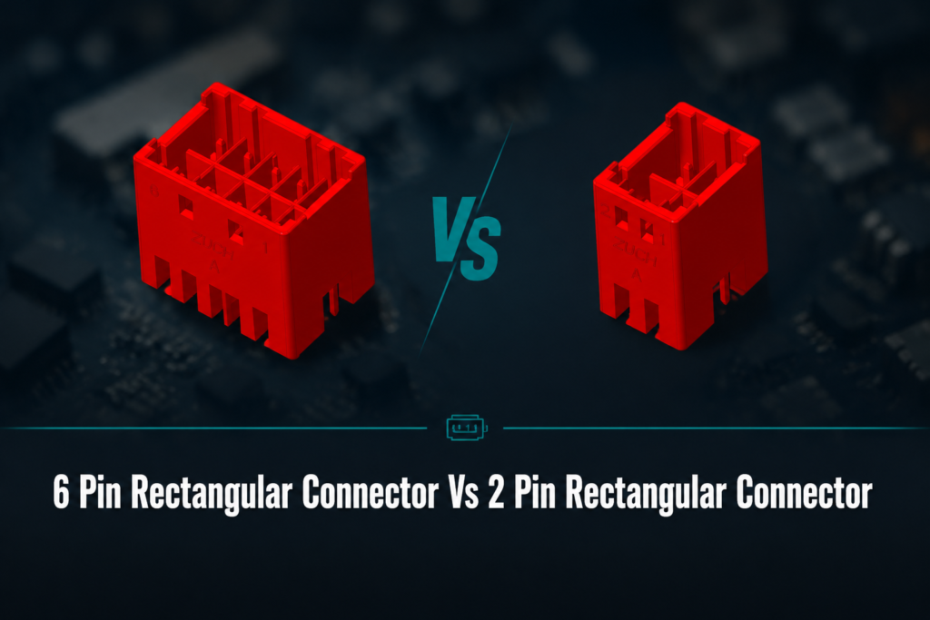
6 Pin Rectangular Connector Vs 2 Pin Rectangular Connector
When a controls engineer in Detroit was redesigning a compact sensor harness, the first prototype used several two-contact plugs because they were familiar and inexpensive. During assembly, technicians mixed two similar plugs, and a later revision needed an additional feedback wire that had nowhere to go. The visible failure looked like a connector-quality problem, but the root cause was selection: pin count, keying, current paths, and service requirements had never been specified together. A two-contact interface can be the cleanest answer for a single circuit; a six-contact interface can consolidate power and signals when the housing, contact system, and pinout are verified. The decision should follow the circuit map and environment, not the contact count alone.
Summary: Choose a 2 pin rectangular connector when the harness genuinely contains one two-wire power or signal circuit and no expansion is expected. Choose a 6 pin rectangular connector when several separately identified circuits must be disconnected as one serviceable assembly. Six contacts do not automatically provide higher current capacity: the datasheet controls contact rating, wire range, temperature limits, and mating conditions. Compare the complete system cost, including terminals, assembly, labeling, testing, and maintenance. Before release, freeze the pinout, confirm polarity and keying, and check the applicable IEC, UL, or vehicle-specific requirements for the destination market.
For a related technical topic, see Modular Rectangular Connectors.
What the pin count actually changes
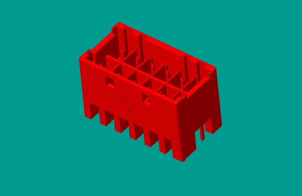
A rectangular connector is a keyed housing and contact system that brings conductors together in a repeatable orientation. A 2 pin rectangular connector normally serves one positive/negative, line/neutral, or two-wire signal path. A 6 pin rectangular connector provides six contact positions that may be assigned to power, return, control, communication, sensing, or reserved circuits. The housing shape does not prove compatibility; contact geometry, pitch, keying, wire termination, and mating half must match.
Pin count also changes documentation and assembly risk. A two-wire harness is easy to continuity-check. A six-wire harness needs a controlled pinout, wire identification, and a check that unused cavities are handled according to the manufacturer’s instructions. In either case, the electrical rating is a property of the complete contact and wire system, not a simple function of the number of pins.
6 pin vs 2 pin: practical comparison
| Decision dimension |
2 pin rectangular connector |
6 pin rectangular connector |
| Circuit role |
One two-wire power or signal circuit |
Several independently assigned circuits in one interface |
| Harness complexity |
Low; polarity and continuity are straightforward |
Moderate; pinout control and wire identification are essential |
| Space at one interface |
Usually the smallest option, subject to the housing family |
One larger interface can replace several smaller plugs |
| Expansion |
Limited unless another connector is added |
Possible only when spare contacts and system documentation justify them |
| Unit-cost tendency |
Often lower for a single circuit; verify the complete assembly cost |
May cost more per housing but reduce parts, labor, and service points |
| Main failure exposure |
Polarity, retention, and contact fit |
All of those plus mis-pinning, crosstalk, and cavity identification |
Selection by application and procurement dimension
| Application dimension |
Prefer 2 contacts when… |
Prefer 6 contacts when… |
Verification action |
| Power only |
There is one defined supply and return |
Several supplies, returns, or auxiliary lines share a service point |
Check contact rating, wire gauge, temperature derating, and polarity |
| Signals and controls |
The device has one simple switch or sensor loop |
Power, control, alarm, and feedback must travel together |
Review the pinout and separate sensitive signals from noisy conductors where required |
| Maintenance |
Technicians can isolate the two conductors safely |
A module should be removed as one labeled harness |
Define labels, test points, and an approved mating/unmating procedure |
| Environment |
Indoor, protected equipment with a suitable unsealed housing |
Outdoor or mobile equipment that needs a verified sealed, keyed family |
Confirm the manufacturer’s environmental test scope; IP claims refer to the assembled system |
Electrical, mechanical, and environmental checks
Start with the circuit list: supply, return, signal, communication, shield, and any genuinely reserved conductors. Then compare the connector datasheet with the wire gauge, insulation diameter, crimp specification, voltage, current, temperature, and mating-cycle requirements. A six-position shell can contain contacts with different ratings, so do not infer a power capability from the shell size.
Mechanical retention matters in vibration and service applications. Confirm the latch, polarization, terminal lock, strain relief, and panel or cable mounting method. For moisture or dust exposure, identify the tested connector configuration and installation conditions; an IP code under IEC 60529 describes ingress protection for the tested assembly and is not a universal product certification.
Use a continuity and polarity check for every production harness. Where the application warrants it, add a crimp-height or pull-test process based on the terminal supplier’s instructions. For signal integrity, review routing and separation rather than assuming that a rectangular housing provides shielding. See the broader electrical connector range for system-level options.
Standards and compliance scope
Standards apply to different questions. IEC 60529 addresses the meaning and testing of IP enclosure ratings; it does not certify every connector carrying an IP label. IEC product or test standards may address connector construction and performance, while UL requirements may apply to a component or end product in a particular North American use. Automotive programs can add OEM, harness, and regional requirements. Ask for the exact standard edition, test configuration, and certificate or report scope instead of treating a logo or supplier statement as proof of universal compliance.
Commercially, an unsupported rating can create redesign, field-service, and liability exposure. Put the destination market, intended equipment, environmental class, and required evidence in the RFQ. The IEC Webstore, IEC standards catalogue, UL Resources, and the relevant vehicle or equipment authority are better starting points than a generic “industrial grade” label.
FAQs
Is a 6 pin rectangular connector better than a 2 pin rectangular connector?
Neither is inherently better. A two-contact part is usually the clearer choice for one two-wire circuit; six contacts are useful when multiple circuits must be keyed and serviced together. Decide from the circuit map, environment, and lifecycle cost.
Can a 2 pin connector carry both power and signal?
It can carry one two-wire differential or combined circuit when the electrical design allows it, but it cannot independently route several power and control lines. Verify the signal method, current, voltage, and insulation requirements before combining functions.
Does a 6 pin connector carry more current?
Not by pin count alone. Current depends on the contact system, wire size, temperature, spacing, and derating rules in the datasheet; unused contacts do not increase the rating of a loaded contact.
Can I adapt a 6-pin connector to an 8-pin connector?
Only when the mating geometry, keying, circuit map, ratings, and unused positions are explicitly engineered for the adapter. Do not use a similarly shaped part as a substitute in power, vehicle, or safety circuits without a documented review.
Conclusion
The decision principle is simple: select the smallest connector architecture that fully and safely expresses the circuit map, while allowing the service and environmental conditions the product will actually face. Begin by listing every conductor, then verify contact and wire ratings, keying, retention, sealing, and the required market evidence. Prototype the harness, perform continuity and polarity checks, and document the pinout before production approval. If the design needs a single removable interface for power plus signals, a six-contact family may reduce assembly and maintenance complexity; if it needs only one two-wire path, a two-contact family avoids unnecessary positions. ZUCH’s product catalogue can help procurement teams compare rectangular connector families and request a drawing-led review for the intended application. For compatible connector families, review the ZUCH product catalogue and request an application-specific drawing review.
References: IEC Webstore (IEC standards and test scope); ISO Standards (international standard catalogue); UL Resources (North American safety and certification guidance); CAN in Automation knowledge (CAN network context).
 Zhejiang ZUCH Technology Co., Ltd.