Zhejiang ZUCH Technology Co., Ltd.
Consider a panel builder adding a second drive to an automated cell. A replacement connector might fit the cutout yet run hotter under the changed load. This is an illustrative design-review scenario, not a reported test result. The problem would not be the rectangular outline alone: load profile, contact arrangement, conductor size and enclosure airflow need review together. A small equipment change can turn a purchasing shortcut into a redesign. Engineers choosing rectangular power connectors need an application-led method: identify the current path, mating frequency, environment, thermal conditions and service access before selecting a housing or pin count.
Summary: Rectangular power connectors serve industrial automation, control cabinets, energy storage and other equipment where organized power and signal interfaces help assembly and maintenance. Their suitability depends on the complete contact system and installation, not on shape alone. Begin with the continuous and transient load, conductor termination, ambient temperature, derating assumptions, ingress exposure and available space. Use the tables below to screen applications, then ask the supplier for drawings and test evidence relevant to the final assembly. Document any assumptions that remain unresolved before approval.
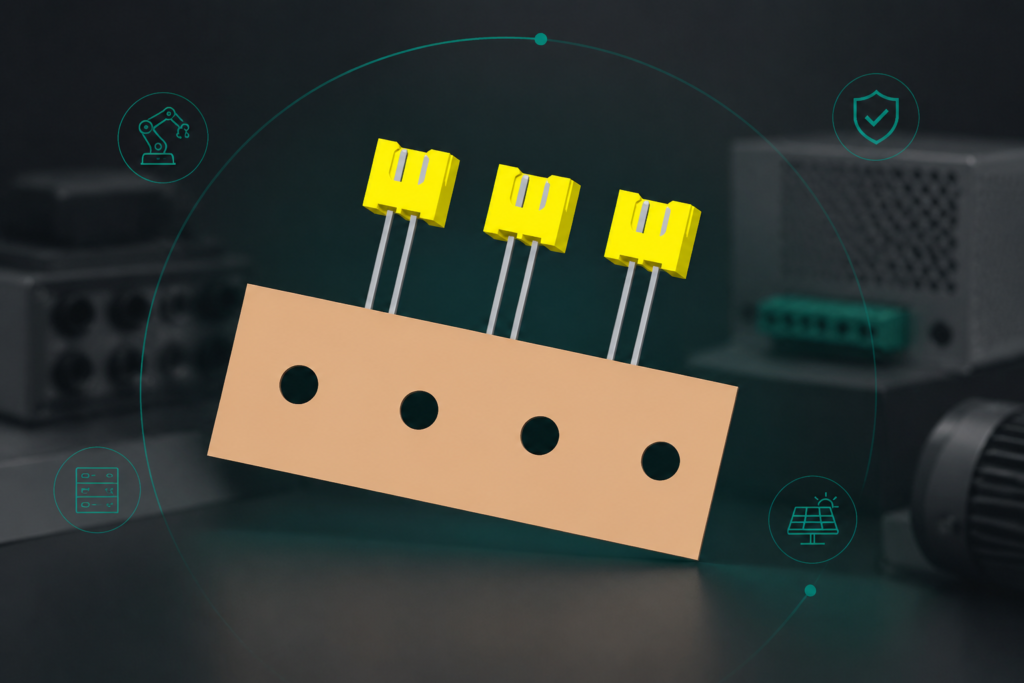
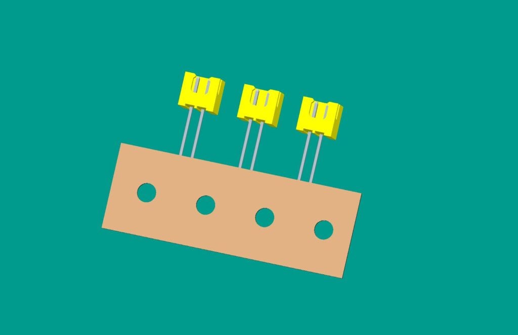
A rectangular housing can separate circuits, support keyed mating and make a dense cabinet layout easier to document. It does not establish a universal rating or a universal current capacity. For a wider connector overview, see rectangular connectors and the related guide on Rectangular Power Connectors in Renewable Energy Systems.
The application sets the power-connector requirements
For rectangular power connectors, application context determines which electrical and mechanical evidence is relevant.
Industrial automation often prioritizes repeated maintenance, clear keying and separation of motor, control and sensor circuits. EV and storage equipment can add high-current DC paths, touch-protection requirements and defined service isolation. A control cabinet may have lower external exposure but tighter thermal and bend-radius constraints. The same connector family should not be assumed suitable across all three without evidence.
| Application | Primary selection question | Typical verification focus |
|---|---|---|
| Industrial automation | Can technicians mate, latch and service the harness without disturbing adjacent circuits? | Keying, retention, contact layout, vibration and maintenance access. |
| EV charging equipment | Is the DC path, protective interlock and environmental exposure defined for the equipment location? | High-current thermal behavior, touch protection, isolation procedure and enclosure interface. |
| Energy storage | How are current, heat, fault isolation and service boundaries managed? | Conductor termination, temperature rise, creepage/clearance and service documentation. |
| Control cabinets | Does the interface fit the panel, wire duct and cooling path? | Envelope, routing, load grouping, derating and inspection space. |
Load, temperature, and termination must be reviewed together
Current capacity is a system result. Contact resistance, conductor cross-section, crimp or screw termination, ambient temperature, adjacent heat sources and duty cycle all affect temperature rise. A catalog value without its test conditions should not be copied into a design limit. Ask which contact arrangement, wire size, assembly method and ambient assumptions produced the value, and whether the customer installation changes them.
For a new design, separate steady-state load from inrush, regenerative or fault conditions. Document the thermal path and the acceptable temperature limit for the equipment. If multiple circuits share a housing, evaluate the worst-case grouping rather than adding individual contact ratings.
| RFQ dimension | Information to state | Selection consequence |
|---|---|---|
| Electrical load | Continuous current, duty cycle, inrush or transient profile and voltage class. | Determines contact system, conductor and validation scope. |
| Thermal environment | Ambient range, enclosure cooling, adjacent heat and grouping. | Sets derating questions and temperature-rise testing. |
| Mechanical interface | Panel cutout, mating direction, keying, latch access and cable bend radius. | Controls housing geometry and service ergonomics. |
| Environment | Indoor/outdoor location, dust, water, vibration and chemicals. | Sets sealing, materials and mounting verification. |
| Lifecycle | Mating cycles, replacement policy and documentation needs. | Balances service time, retention features and spare strategy. |
Standards define methods and scope, not a universal current rating
Start with the equipment standard and destination market, then identify connector-specific requirements. IEC Webstore is the authoritative catalog for relevant IEC publications; the applicable document may address low-voltage equipment, industrial machinery, enclosures or a connector family. IEC 60529 can describe enclosure ingress protection, but it is not a current-carrying certification.
Use ISO Standards for management and terminology references where applicable, and review UL Resources when a North American project asks for UL recognition or listing. Confirm the exact product scope, conditions of acceptability and installation limits. A supplier’s general compliance statement is not a substitute for project-specific evidence.
Use a short application screen before requesting samples
- Draw the power and signal paths, including protective earth or interlock conductors where relevant.
- Record load, duty cycle, ambient and grouping assumptions; identify the worst case.
- Check the mechanical envelope, mating direction, cable routing and maintenance clearance.
- Specify environmental exposure and the required enclosure or interface test scope.
- Request drawings, assembly instructions, material information and test evidence for the exact configuration.
ZUCH can be considered during this comparison when the project needs configurable contact layouts, drawings or sourcing support. The correct choice remains the one that satisfies the application’s electrical, mechanical and evidence requirements.
Questions engineers ask about rectangular power connector applications
Which industries use rectangular power connectors?
They are used across automation, control cabinets, energy equipment, transportation and other machinery where a structured multi-contact interface is useful. The correct family still depends on load, environment and service requirements.
How do I size a rectangular power connector for load?
Start with the complete current path and its conditions: contact, termination, wire, ambient, grouping and duty cycle. Use supplier data and a defined temperature-rise or equipment validation method rather than a shape-based estimate.
Can these connectors be used outdoors?
Only when the assembled connector and host enclosure have evidence for the intended exposure. Check sealing, cable entry, UV or chemical compatibility and maintenance conditions; an indoor-rated component is not automatically outdoor-ready.
What should a supplier quote include?
Provide the mating interface, contact layout, wire range, load profile, environmental conditions, drawing envelope, keying and required evidence. This makes options comparable and exposes assumptions before tooling or sampling.
What is the difference between a power connector and a signal connector in the same housing?
The housing outline does not decide the duty. Power contacts, conductor size, temperature rise, insulation coordination and termination process must be specified for the power path, while signal circuits may have different contact, shielding and noise requirements. Treat mixed power-and-signal layouts as a configuration to validate rather than assuming every cavity is interchangeable.
How should I compare connector options when the load is intermittent?
Record the duty cycle, inrush or transient profile, ambient temperature and cooling conditions before comparing current claims. Ask for temperature-rise and contact-resistance evidence for the intended configuration, then verify the protection and conductor selection; a short average load does not by itself establish the connector's allowable peak duty.
References
- IEC 60512-1: Electrical connectors and components — Tests and measurements
- IEC 60512-2-1: Contact resistance test method
- UL 1977: Component connectors for use in data, signal, control and power applications
- CAN in Automation: CAN knowledge and application context
Decision summary for rectangular power connector applications
Choose by application evidence, not by the rectangular outline. First identify the load path, thermal assumptions, mating and service pattern; then verify the housing, contacts, termination and host enclosure as one assembly. For EV or storage equipment, make protective and isolation boundaries explicit. For cabinets and automation, give equal weight to routing, keying and maintenance access. Once those conditions are documented, compare drawings and test evidence with suppliers. Review ZUCH’s rectangular power connectors at the product range when you are ready to align a candidate with the actual RFQ, and request clarification wherever a rating or compatibility claim lacks a defined scope. This record also helps purchasing and engineering use the same acceptance criteria.