Zhejiang ZUCH Technology Co., Ltd.
Consider an intermittent charger shutdown that does not appear during a static check but occurs after cable movement or a higher equipment-bay temperature. This is an illustrative diagnostic scenario, not a reported fault or test. The connector outline alone would not explain it; engineers would need to review interface retention, protective interlock and thermal assumptions as one assembly. Teams choosing rectangular connectors for EV charging systems should therefore begin with the equipment boundary and service procedure, then verify the connector, cable entry and enclosure under the conditions the charger will actually see.
Summary: Rectangular connectors for EV charging systems can organize DC power, auxiliary circuits and service interfaces where the equipment design supports them. Suitability is conditional: the connector must match the specified current path, temperature, touch-protection concept, interlock strategy, environmental exposure and maintenance access. A connector shape does not establish high-current capability or EV compatibility. Define the charger architecture and validation scope in the RFQ, and treat any IP, current or safety statement as applicable only to the documented configuration. Confirm the responsible equipment team’s acceptance criteria.
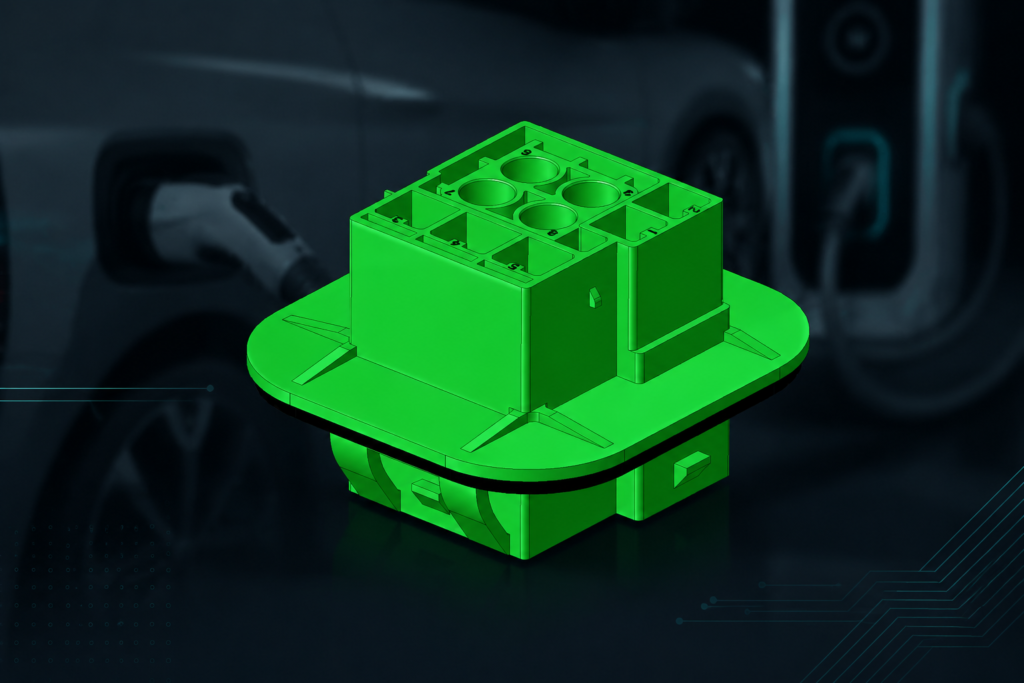
Rectangular connectors can support clear keying, modular contact layouts and controlled routing inside a charger or cabinet. They are not automatically a substitute for a vehicle inlet, a charging coupler or a certified safety component. Compare the interface with the actual equipment function and the destination-market requirements. The related article Industrial Rectangular Connectors for Heavy-Duty Applications provides additional context on industrial installation constraints.
Map the charger boundary before choosing a connector
For rectangular connectors for EV charging systems, map the equipment boundary before comparing a catalog family.
Separate the vehicle-facing charging interface from internal power distribution, auxiliary control and service disconnect functions. Each boundary can have a different mating frequency, exposure, touch-protection need and validation method. A connector used inside a protected cabinet may have a different duty from a connector mounted near a cable gland or cooling path. Document where the interface sits, who can access it and what happens during a fault or maintenance operation.
| Interface role | Questions for the design team | Evidence to request |
|---|---|---|
| DC power distribution | What continuous, transient and fault conditions reach the contacts? | Contact and termination data, thermal assumptions and validation plan. |
| Auxiliary control | Are signal, communication and power circuits separated and keyed? | Pinout, keying, shielding or isolation requirements and drawings. |
| Service interface | How is the circuit made safe before a technician opens or mates it? | Service procedure, retention, touch-protection and interlock logic. |
| External or exposed interface | What dust, splash, condensation, UV or cleaning exposure occurs? | Enclosure/interface test scope and cable-entry details. |
DC current and heat require configuration-specific evidence
High-current DC selection is a complete-path problem. Contact resistance, conductor termination, ambient temperature, grouping, airflow and duty cycle can all change temperature rise. Use supplier data only with its stated wire size, assembly method and conditions. A current number detached from those conditions is not a design guarantee. Where the charger has sustained load or restricted cooling, define a thermal validation method before approving the connector.
HVIL or another protective interlock may be part of the equipment safety concept, but the connector alone does not prove that the system is safe. Confirm how the interlock is wired, how loss of continuity is detected, and how service personnel are protected. Touch protection should be evaluated at the mated, unmated and partially serviced states relevant to the equipment.
| Selection dimension | Specify in the RFQ | Do not infer from |
|---|---|---|
| Electrical | Voltage class, continuous and transient current, duty cycle and conductor termination. | Housing size or pin count alone. |
| Protection | Touch-protection concept, interlock boundary and service isolation sequence. | A “high-voltage” label without a system description. |
| Environment | Location, water or dust exposure, condensation, chemicals, UV and cleaning. | An IP code copied without the test configuration. |
| Mechanical | Keying, latch access, cable bend radius, vibration and available clearance. | Visual similarity to another charger part. |
| Lifecycle | Mating cycles, inspection, replacement and spare-part control. | A generic claim of “maintenance-free.” |
Separate EV charging equipment from vehicle inlet standards
Charging equipment may be subject to different standards depending on its architecture, market and installation. Start with the applicable equipment and installation requirements, then identify connector or enclosure standards. The IEC Webstore is the source for current IEC publications; it does not turn a connector catalog page into a certification. If an IP classification is claimed, define the IEC 60529 test scope and the exact assembled sample.
For North American projects, review the relevant UL Resources and verify the exact product category, file scope and conditions of acceptability. Use ISO Standards for applicable quality or environmental management references. The correct compliance path remains dependent on the charger, installation and destination market; do not imply a vehicle-wide approval from a component statement.
Build the RFQ around current path, protection, and service
- Show the equipment boundary and identify vehicle-facing, internal, auxiliary and service interfaces.
- State electrical load profiles, conductor details, ambient and cooling assumptions.
- Describe touch protection, interlock or isolation functions as system requirements.
- List exposure, cleaning, vibration and maintenance conditions; identify the assembled IP test scope if required.
- Request drawings, keying, material information, assembly instructions and evidence for the exact configuration.
ZUCH can be considered when the project needs a documented rectangular interface or configurable contact arrangement. Any proposed part should be reviewed against the charger design and validated by the responsible equipment team.
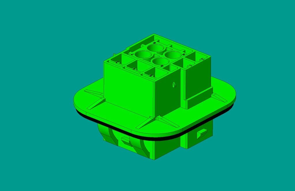
Questions engineers ask about rectangular connectors in EV chargers
Where might rectangular connectors be used in an EV charger?
They may be used for internal power distribution, auxiliary control or service interfaces when the equipment design and evidence support that use. The vehicle-facing coupler and the internal connector are different functions and should not be conflated.
Can any rectangular connector carry high-current DC?
No. Confirm the complete contact, termination, conductor, ambient and duty-cycle conditions. A housing shape or catalog family does not establish a safe current limit for a particular installation.
Does an IP rating prove a charger connector is safe?
No. IP classification addresses defined ingress tests. Touch protection, isolation, interlock operation, thermal behavior and the host enclosure require their own requirements and verification.
Are rectangular automotive connectors compatible with every EV?
No. Compatibility requires matching the interface geometry, pinout, keying, electrical limits, control functions and vehicle or charger requirements. Never infer compatibility from a similar appearance.
What should be checked during maintenance?
Follow the equipment isolation procedure, then inspect latch engagement, seals, cable entry, contacts and signs of heat or contamination. Record any replacement and confirm the reassembled interface meets the documented condition.
Should a rectangular connector be used as the vehicle charging coupler?
Do not infer that use from the rectangular outline. A vehicle charging coupler is governed by its applicable charging-interface requirements, communication and protection architecture, while a rectangular connector may instead be used inside charger equipment or a serviceable cabinet. Confirm the equipment boundary and the responsible compliance requirements before selecting the connector family.
References
- IEC 61851-1: Electric vehicle conductive charging system — General requirements
- IEC 60512-1: Electrical connectors and components — Tests and measurements
- UL 1977: Component connectors for use in data, signal, control and power applications
- U.S. Department of Energy: Transportation Technologies Office
Decision summary for EV charging connector selection
The governing principle is to treat the connector as one element in a charging-system boundary. First judge whether the proposed location, exposure and service function require a rectangular interface; then verify current path, temperature, touch protection, interlock behavior and maintenance access. Separate proven facts from assumptions, especially when an IP or current claim is copied from a different assembly. Once the RFQ captures those conditions, review candidates and validation evidence together. You can examine ZUCH’s rectangular connectors for EV charging systems at the product range as a sourcing input, then confirm final compatibility and safety through the charger owner’s documented engineering process. Keep the approved configuration and service limits with the equipment record.