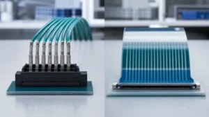
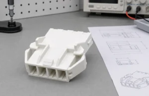
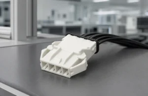
A connector housing is chosen through three lenses at once: material behaviour, error-proofing features and terminal retention. Score candidates against all three before price enters the discussion.
Contents
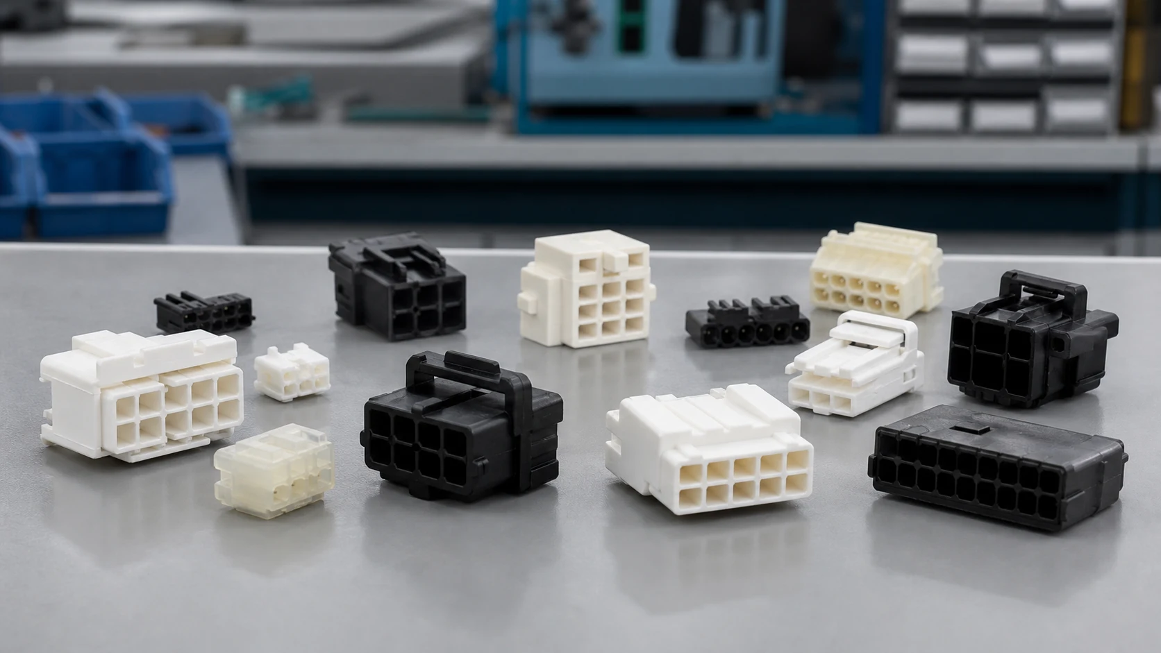
The housing positions terminals, insulates circuits, carries locking and keying geometry, and shields contacts from handling. Electrical behaviour is credited to terminals, yet most field complaints trace back to housing fit, retention or damage.
| Selection lens |
Questions to close |
Evidence to request |
| Material |
Temperature, moisture, chemicals, flammability |
Compound designation and data |
| Error-proofing |
Keying options, colours, orientation |
Keying chart and samples |
| Retention |
Lance type, secondary lock, pull force |
Retention specification and trial results |
Part 2. Which material properties matter for the application?
Review temperature range, moisture exposure, chemical contact, flammability class and mechanical toughness against the operating profile. Ask for the specific compound designation rather than a generic polymer family name, because fillers and grades change behaviour.
Part 3. How do keying and polarization prevent build errors?
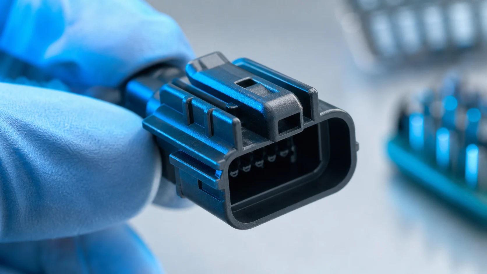
Keys, ribs and asymmetric shapes make wrong mating physically impossible instead of procedurally forbidden. Where several similar housings sit near each other, assign distinct key options and colours so operators cannot swap them.
Part 4. How do terminal retention and locking work together?
Primary retention comes from the terminal lance or the housing cavity, and some designs add a secondary lock that confirms full seating. Match the retention system to wire loads and service handling, and verify seated terminals against the specified pull requirement.
| Feature |
Purpose |
Verification |
| Polarization rib |
Blocks reversed mating |
Mating trial with counterpart |
| Secondary lock |
Confirms terminal seating |
Seating audit and pull check |
| Latch with tactile click |
Confirms full mating |
Assembly trial and service action |
Part 5. Which environmental exposures should be stated?
State temperature extremes, humidity, cleaning agents, vibration and any sealing expectation explicitly in the drawing or specification. Sealed families need mating-interface, wire-seal and cavity-plug definitions as a set, not as afterthoughts.
Important: General guidance cannot approve a specific design or lot. This is a source-note application of the IPC and TE Connectivity references listed below; apply it through your controlled drawing and acceptance plan.
Part 6. What should the housing section of an RFQ contain?
List the housing part definition, compound, keying option, retention features, mating counterpart and acceptance checks. Add samples and fit trials with the actual terminals and wires, because paper compatibility does not guarantee assembly behaviour.
Part 7. Which ZUCH route supports a housing inquiry?
Use ZUCH’s Housing category and the live product catalogue to identify relevant connector, terminal or housing component families. These are discovery routes only and do not demonstrate that a specific configuration is approved for your application.
RFQ inputs
- Housing definition with compound, keying option and colour.
- Terminal and wire combinations with retention requirements.
- Environmental exposures, sealing needs and mating counterpart.
- Samples, fit-trial plan and acceptance records expected.
Fit Boundary
This guide supports engineering and sourcing discussion; it cannot replace programme-specific validation, market requirements, or an approval record. Use ZUCH’s sample request route or contact page for controlled component documentation and samples.

FAQ
What does a connector housing actually do?
It positions and insulates terminals, provides locking and keying geometry, and protects contacts through handling and service.
How do I choose a housing material?
Match compound-level data to temperature, moisture, chemical, flammability and toughness requirements from the operating profile.
What is the purpose of housing keying options?
Distinct keys make incorrect mating physically impossible where similar connectors sit close together.
What is a secondary lock in a housing?
An additional feature that verifies terminals are fully seated and adds retention beyond the primary lance.
How is terminal retention verified?
By seating audits and pull checks against the specified requirement using the actual terminal and wire combination.
Do sealed housings need special definition?
Yes. Interface seals, wire seals and cavity plugs must be specified together and validated as a system.
What belongs in a connector housing RFQ?
Housing and compound definition, keying, retention, environmental needs, counterpart, samples and acceptance checks.
References
 Zhejiang ZUCH Technology Co., Ltd.