Fine-Pitch Connector Mating Cycles: How Durability Changes Product Design
Define actual assembly, fixture, service, and repair cycles before selecting a fine-pitch interface. Use the drawing, intended operating conditions, and validation plan before comparing component options.

Contents
Mating-cycle durability is not a catalogue checkbox to copy into a product requirement. It describes a use scenario that must match actual service, assembly, repair, fixture, and operator-access conditions. Define the expected number and type of mate/unmate events before selecting a component.
| Review area |
Buyer needs to define |
Why it matters |
| Mating interface |
Both halves, orientation, and operating condition |
Prevents an incomplete component comparison |
| Electrical behavior |
Signal or durability conditions and acceptance basis |
Keeps claims tied to the actual system |
| Mechanical envelope |
Board, enclosure, cable, and access constraints |
Reveals installation conflict before release |
| Evidence |
Samples, drawings, test plan, and change control |
Makes supplier responses comparable |
Which operating scenarios create the most wear?
Production assembly, end-of-line test, field service, prototype debugging, and repeated fixture use can each add cycles. Misalignment, side load, cable pull, and a difficult access angle can increase contact or housing stress even if the nominal cycle count appears modest.
How do alignment and retention affect durability?
Fine pitch reduces geometric tolerance. Polarization, guides, latch condition, insertion path, board support, and cable routing all affect whether contacts engage as intended. A mating system should be checked in its housing, enclosure, and service position rather than only on a loose sample. For a related technical reference, see Small Pitch Connectors: Signal Integrity Risks Engineers Should Check First. For a related technical reference, see Pin Header vs Socket Header: When Each Board Connection Makes Sense.

| Review input |
Question for engineering |
RFQ output |
| Interface geometry |
What must stay aligned or controlled? |
Drawing and mating-half definition |
| Environment |
What exposure and handling apply? |
Conditions and protection boundary |
| Validation |
What must be demonstrated? |
Sample, method, and acceptance plan |
What contamination and environment questions should be asked?
Dust, handling residue, moisture, chemicals, vibration, temperature cycling, and storage conditions can change the contact environment. State the expected exposure and cleaning restrictions. Do not convert a material description into a blanket environmental approval.
How should test fixtures represent the real task?
A cycle fixture should reproduce the relevant mating half, alignment path, speed, force direction, cable condition, and inspection intervals. If a service technician uses a different access angle from a production fixture, consider both conditions in the validation plan.
Important: General connector guidance cannot approve a particular finished design. This is a source-note application of the TE and IPC references listed below; define the project-specific method, samples, and acceptance criteria.
What evidence is needed before release?
Define the sample configuration, test sequence, inspection method, electrical/mechanical acceptance criteria, records, and changes that require re-evaluation. The project owner must decide whether the evidence is for prototype learning, pilot release, or serial approval.
Which ZUCH product route supports a controlled inquiry?
Use ZUCH’s Small Pitch Connectors route and the live product catalogue to identify a possible component family. These are discovery routes only; they do not prove a specific interface is qualified for the final product.
RFQ inputs
- Controlled mating-interface, drawing revision, and application condition.
- Electrical, mechanical, environmental, and service constraints.
- Required samples, drawings, validation method, and acceptance criteria.
- Required production, traceability, and change-control evidence.
Fit Boundary
This guide supports a structured engineering and sourcing discussion. It cannot replace programme-specific qualification, regulatory review, or an approved validation record. Send controlled inputs through ZUCH’s sample request route or contact page.
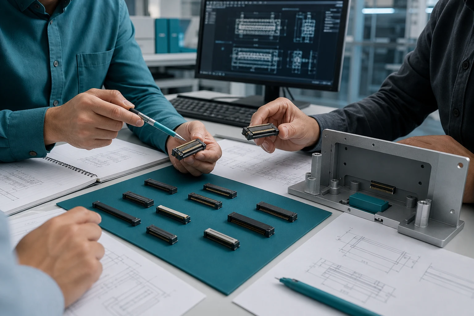
Define the service task before accepting a mating-cycle claim
A mating-cycle number has meaning only when the test represents the real connector, alignment, speed, force, contamination, mating counterpart, and inspection method. A higher number from a different product family or fixture cannot be treated as a universal durability ranking.
| Durability input |
What to define |
Why it matters |
| Service profile |
Expected mating/unmating events, access frequency and operator method |
A production assembly and a field-service connector experience different wear |
| Alignment |
Keying, guide features, allowable angular error and insertion path |
Side loading can create wear before the nominal cycle count is reached |
| Environment |
Dust, moisture, chemicals, temperature and vibration exposure |
Contamination and movement can change contact behavior |
| Inspection |
Visual wear, retention, contact resistance, continuity and functional checks |
A cycle count alone does not define end-of-life |
FAQ
Does a higher mating-cycle number guarantee reliability?
No. Cycle ratings are test-condition-specific. Confirm the mating counterpart, alignment, rate, load, environment, acceptance limits and inspection method before comparing values.
Why do alignment features matter for fine-pitch durability?
Fine-pitch interfaces have less room for angular or lateral error. Guides and keying can reduce side loading, but their effectiveness must be checked with the actual housing and service procedure.
Can a test fixture create extra connector wear?
Yes. A fixture can add misalignment, unequal force, contamination or an unrealistic insertion path. Review fixture repeatability and compare the motion with the intended assembly or service task.
What should be inspected after durability cycling?
Use the applicable product and program criteria for contact resistance, continuity, retention, visible damage, mating force or functional performance. Do not invent a universal pass/fail limit.
What are mating cycles for a fine-pitch connector?
They are the defined number of intended mate/unmate events for a specific component and application condition. They should reflect assembly, test, service, and repair use.
Why do alignment features matter for durability?
Poor alignment can create side loading or incomplete engagement, increasing stress on small contacts and housings during repeated use.
Does a higher cycle number guarantee reliability?
No. The full application includes the mating half, access path, cable load, environment, handling, and validation conditions.
Can test fixtures create extra wear?
Yes. A fixture with a different insertion path, speed, or alignment from the real task can produce unrepresentative wear or hide a real access problem.
Should service cycles be included in the requirement?
Yes. Include expected field service, inspection, and repair activity if the product is designed to be disconnected after production.
What should be inspected after durability cycling?
Use the controlled plan to assess contact condition, latch/retention behavior, mating operation, and the electrical or mechanical characteristics relevant to the application.
What should buyers include in a durability RFQ?
Include the mating interface, cycle scenarios, alignment and access constraints, environment, fixture/test conditions, acceptance plan, required evidence, and change-control expectations.
Key takeaway
Approve fine-pitch durability against the real service task and a defined post-cycle inspection. Cycle count, alignment, environment, mating counterpart, fixture, and end-of-life criteria belong in the same validation record.
References
 Zhejiang ZUCH Technology Co., Ltd.