PCB Terminals Explained: Types and PCB Headers Selection Guide
As electronic devices continue to become smaller, faster, and more intelligent, reliable PCB interconnection technology has become a critical factor in electronic system performance. From industrial automation and automotive electronics to AI servers and high-speed computing platforms, the quality of PCB connection solutions directly affects signal integrity, power efficiency, and product reliability.PCB Terminals and PCB connectors are two essential components used to establish electrical connections between printed circuit boards, wires, and electronic modules. Although they are often discussed together, they serve different purposes in electronic design.This guide explains what PCB terminals are, the differences between PCB terminals and PCB connectors, common connector types, PCB header selection methods, and emerging trends in high-speed computing applications. For a related technical reference, see A Complete Guide to PCB Connector Types and Selection.
What Are PCB Terminals? Understanding Their Role in PCB Connectivity
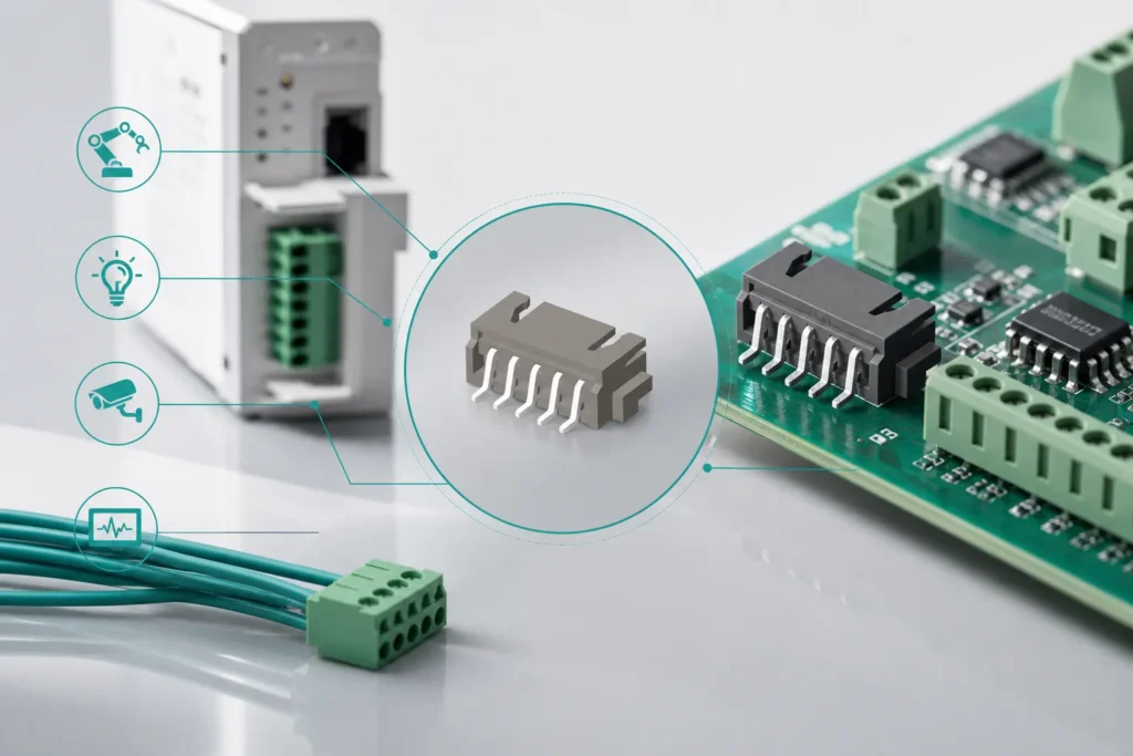
PCB Terminals are electrical connection components mounted on printed circuit boards (PCBs) to provide reliable interfaces between the PCB and external wires, cables, or electronic modules.
Compared with direct solder connections, PCB terminals provide greater flexibility, easier maintenance, and improved reliability. They are commonly used for power transmission, signal connection, and modular wiring solutions in various electronic systems.
Typical applications include:
-
Industrial control systems
-
Power supply equipment
-
Automotive electronic modules
-
Sensors and embedded devices
-
Communication equipment
A PCB terminal usually consists of several key components:
| Component |
Function |
| Contact element |
Provides electrical conductivity and signal transmission |
| Housing |
Provides insulation and mechanical protection |
| Mounting structure |
Enables SMT or through-hole PCB installation |
| Locking mechanism |
Prevents accidental disconnection |
Modern PCB terminals must meet increasingly demanding requirements, including higher current capacity, smaller size, improved thermal performance, and stronger environmental resistance.
PCB Terminals vs PCB Connectors: What Is the Difference?
Although PCB terminals and PCB connectors are sometimes used interchangeably, they have different design purposes.
PCB terminals are mainly designed for wire termination and stable electrical connection, while PCB connectors focus on detachable, modular, and flexible interconnection between electronic components.
According to connector design principles from Molex Connector Solutions, connector selection should consider electrical performance, mechanical requirements, environmental conditions, and the specific application environment.
| Feature |
PCB Terminals |
PCB Connectors |
| Main purpose |
Electrical termination |
Modular electrical connection |
| Connection type |
Wire-to-board connection |
Board-to-board or cable connection |
| Maintenance |
Usually fixed installation |
Easy replacement and service |
| Typical applications |
Industrial control, power systems |
Servers, communication, consumer electronics |
| Design focus |
Current carrying capability |
Flexibility and signal performance |
When Should You Choose PCB Terminals?
PCB terminals are suitable when:
-
High current transmission is required
-
Long-term stable wiring is needed
-
Strong mechanical retention is important
-
Equipment operates under harsh conditions
For example, industrial automation equipment often uses PCB terminal blocks because they provide reliable connections under vibration, temperature variation, and continuous operation.
When Should You Choose PCB Connectors?
PCB connectors are preferred when:
-
Components require frequent replacement
-
Modular design is needed
-
Space efficiency is important
-
High-speed signal transmission is required
Modern computing systems, communication devices, and advanced electronics rely heavily on PCB connectors for high-density interconnection.
Different Types of PCB Terminals and PCB Connectors Explained
PCB Terminal Blocks
PCB terminal blocks are one of the most widely used PCB terminal solutions, especially in industrial applications.
Common types include:
Compared with traditional wiring methods, modern terminal blocks provide faster installation, improved safety, and better resistance against vibration.
Typical applications include:
Wire-to-Board PCB Terminals
Wire-to-board connectors provide electrical connections between external cables and PCB assemblies.
Their advantages include:
These connectors are commonly used in:
Crimp terminal technology is widely adopted because it provides low contact resistance and stable electrical performance.
Contact Resistance:The electrical resistance generated at the interface between two contacting conductive surfaces.
Board-to-Board Connectors
Board-to-board connectors enable direct electrical connections between two PCBs without additional wiring.
Common structures include:
-
Vertical connectors
-
Horizontal connectors
-
Mezzanine connectors
They are widely used in high-density electronic systems where PCB space is limited.
Important selection factors include:
-
Contact pitch
-
Mating cycles
-
Signal speed
-
Mechanical alignment
Applications include:
-
Smartphones
-
Embedded systems
-
Medical equipment
-
Servers
PCB Headers and Pin Headers
PCB headers are among the most common PCB connector solutions because of their simple structure, cost efficiency, and reliability.
Common PCB header types include:
-
Male pin headers
-
Female headers
-
Straight headers
-
Right-angle headers
-
SMT headers
-
Through-hole headers
PCB headers are widely used in:
-
Development boards
-
Industrial controllers
-
Communication modules
-
Embedded systems
PCB Header Selection Guide: How to Choose the Right PCB Header
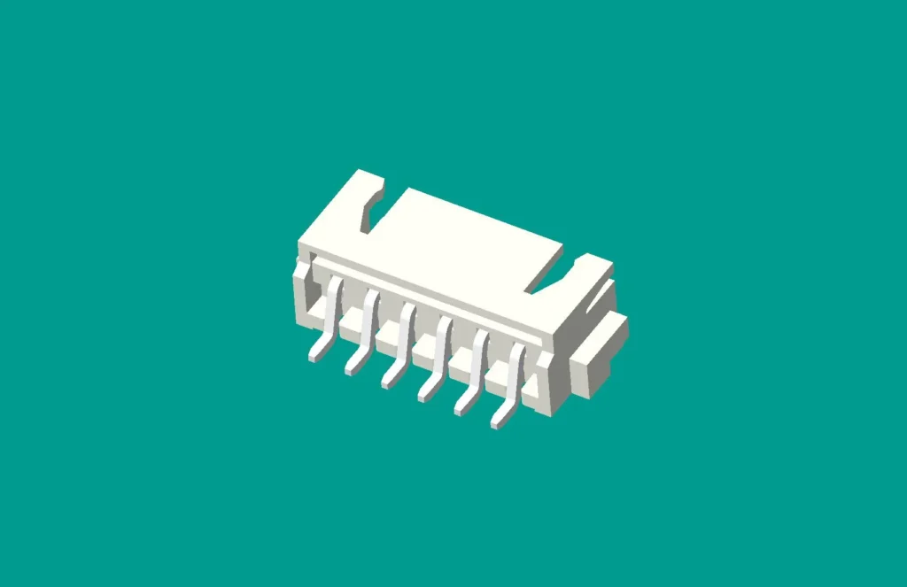
Selecting the correct PCB header requires evaluating electrical performance, mechanical requirements, and manufacturing processes.
Industry recommendations from TE Connectivity PCB Connector Solutions emphasize that factors such as pitch size, mounting technology, current rating, and environmental reliability are critical when selecting PCB connectors.
Choosing PCB Header Pitch and Pin Configuration
Pitch refers to the distance between two adjacent pins. Smaller pitch allows higher connection density but requires more precise PCB manufacturing.
| Pitch Size |
Typical Applications |
| 2.54 mm |
Development boards and general electronics |
| 2.00 mm |
Compact industrial systems |
| 1.27 mm |
High-density electronic devices |
| ≤1.00 mm |
Advanced miniaturized products |
Engineers should select pitch according to PCB space limitations, signal requirements, and assembly capability.
SMT vs Through-Hole PCB Headers
| Type |
Advantages |
Applications |
| Through-hole PCB Header |
Higher mechanical strength |
Industrial equipment, high vibration environments |
| SMT PCB Header |
Supports automated assembly |
Compact and high-volume electronics |
Through-hole headers are preferred when mechanical strength is critical, while SMT headers provide better compatibility with modern automated PCB production.
Electrical and Mechanical Selection Factors
Important parameters include:
-
Rated current
-
Rated voltage
-
Contact resistance
-
Operating temperature
-
Mechanical durability
-
Number of mating cycles
For high-reliability systems, connector selection should consider actual operating environments rather than only basic electrical specifications.
What high-speed and AI-server boards add to connector selection
The rapid growth of artificial intelligence, cloud computing, and data centers has created new requirements for PCB connector technology.
AI servers require extremely high processing capability, which leads to:
-
Higher data transmission rates
-
Increased power density
-
More demanding thermal management
-
Higher connector reliability requirements
Traditional PCB connectors designed for low-speed applications may not meet the requirements of modern AI hardware.
AI Server:A computing system optimized for artificial intelligence workloads, requiring high-performance processors, memory, and high-speed interconnects.
High-Speed Signal Integrity Challenges
High-speed computing systems require PCB connectors with:
High-speed connector technologies from Samtec High-Speed Connector Technology Resources highlight the importance of signal integrity, impedance control, and mechanical reliability in advanced computing applications.
Controlled Impedance:A PCB design technique that maintains consistent electrical impedance to reduce signal reflection and transmission loss.
Poor connector design can cause:
-
Signal attenuation
-
Crosstalk
-
Data transmission errors
-
System instability
Signal Integrity:The ability of an electrical signal to maintain its quality and accuracy during transmission.
Thermal and Mechanical Reliability
AI servers operate continuously under high workloads, creating additional challenges for PCB connectors.
Advanced connector designs increasingly focus on:
-
Improved contact materials
-
Higher current capability
-
Better heat dissipation
-
Long-term mechanical stability
Future server and computing platforms will require connectors capable of supporting higher bandwidth and greater power delivery.
What current PCB connector trends change the selection decision
PCB terminal and connector technology is evolving toward higher density, faster transmission, and improved sustainability.
Miniaturization and High-Density Connections
Modern electronic products require smaller components with more connection points. Future PCB terminals will continue moving toward:
High-Speed Data Transmission
The development of AI, 5G, cloud computing, and edge computing is increasing demand for high-speed PCB connectors with excellent signal integrity performance.
Sustainable Connector Design
Environmental requirements are also influencing connector development.
Future solutions will focus on:
A practical PCB terminal selection workflow for the first design review
Current PCB connector searches tend to split into four decisions: pitch and density, termination method, electrical load, and assembly process. Resolve them in that order so a compact header is not selected before the board and manufacturing constraints are understood.
| Decision |
Questions to answer |
Evidence to keep |
| Interface |
Board-to-wire, board-to-board, terminal block, header or socket? |
Mating drawing and pin/cavity map |
| Geometry |
What pitch, row arrangement, keying and keep-out are required? |
PCB land pattern, 3D model and mating clearance |
| Electrical |
What current, voltage, signal speed and temperature apply? |
Datasheet conditions and derating assumptions |
| Assembly |
Through-hole, SMT, wave, reflow, press-fit or hand insertion? |
Approved footprint and process window |
| Service |
Will the connection be unplugged, probed or replaced in the field? |
Retention, access and replacement plan |
Fine pitch can save board area, but it also narrows the assembly and inspection margin. Confirm solder-joint access, coplanarity, polarity marking and rework access with the manufacturing team before releasing the footprint. For high-speed or dense boards, keep the connector choice tied to the complete signal path; a connector label alone does not establish signal-integrity performance.
A good design review ends with a controlled part number, a verified land pattern, the mating part, and a written list of conditions that are still open. Those four items make a PCB terminal comparison auditable instead of appearance-driven.
Pitch does not establish electrical suitability
A smaller pitch can improve density, but the release decision still depends on conductor size, current and voltage conditions, creepage/clearance, PCB thickness, solder process, mating geometry and service access. Use the exact product datasheet and the applicable insulation-coordination or terminal-block requirements when checking the rating; do not transfer a value from a visually similar header.
PCB terminal questions engineers ask before release
How should I verify PCB header pitch before ordering?
Use the manufacturer drawing or a verified footprint, and confirm the center-to-center spacing, row arrangement, pin count, keying and mating part together. A visual estimate from a photograph is not enough for release.
Should I choose a through-hole or SMT PCB header?
Choose from the assembly process and mechanical load, not habit. Review solder process, board thickness, retention, rework access, vibration and the manufacturer’s approved land pattern before selecting the termination style.
Does a smaller PCB connector pitch always save board space?
Not necessarily. Smaller pitch can increase routing, inspection and solder-process sensitivity. Compare the complete keep-out, escape routing, mating access and production capability before treating density as the only objective.
What evidence is needed for a PCB connector used in a high-speed design?
Request the connector electrical data under the relevant conditions, the mating configuration, layout guidance and any application-specific validation. A generic “high-speed” label does not establish performance for your board stack-up or channel.
What is the difference between PCB terminals and PCB connectors?
PCB terminals are mainly used for wire termination and stable electrical connections, while PCB connectors provide detachable and modular connections between electronic components.
What are the most common PCB header types?
Common PCB header types include male headers, female headers, straight headers, right-angle headers, SMT headers, and through-hole headers.
How do I select the right PCB terminal?
Selection should consider current rating, voltage requirements, pitch size, mounting method, environmental conditions, and reliability requirements.
Why are PCB connectors important in AI servers?
AI servers require high-speed data transmission, high-density connections, and stable power delivery. Advanced PCB connectors help maintain signal integrity and system reliability under demanding workloads.
Key takeaway
PCB terminal selection is a system decision. Lock the interface, pitch, electrical conditions, assembly process and service requirement together, then release the verified footprint and mating part as one controlled package.
References
-
IPC Standards for Printed Circuit Board Design and Assembly
Industry standards covering PCB manufacturing, assembly, reliability, and electronic interconnection requirements. For a related technical reference, see Comprehensive Guide to PCB Board Connector Types.
-
Molex Connector Solutions and Technical Resources
Technical resources covering PCB connectors, terminals, and electrical interconnection solutions.
-
TE Connectivity PCB Connector and Terminal Solutions
Engineering information related to PCB headers, terminals, connector design, and industrial applications.
-
Samtec High-Speed Connector Technology Resources
Technical resources related to high-speed connectors, signal integrity, and advanced computing applications.
- Phoenix Contact PCB terminal block documentation
- IEC 60947-7-1: Terminal blocks for copper conductors
- IEC 60664-1: Insulation coordination
 Zhejiang ZUCH Technology Co., Ltd.