RAST Connector Termination: Compare IDC and Crimp Interfaces by System
IDC and crimp should be compared as complete termination systems, not as interchangeable labels. The controlled connector interface, conductor definition, assembly method, inspection plan, and service context determine the questions a project must resolve.
Contents
Part 1. Define the controlled termination system
The starting point is the released connector, conductor, termination definition, and intended assembly route. A termination label by itself does not define wire construction, tooling, connector geometry, inspection conditions, or the evidence needed for the finished assembly.
Document the exact configuration under review. That gives engineering and purchasing a common basis for comparing a supplier response, sample request, or proposed alternate.
| System input |
Why it matters |
Controlled record |
| Connector interface |
Identifies the defined termination relationship |
Connector drawing and revision |
| Conductor definition |
Connects the method to the actual wire system |
Wire construction and controlled requirement |
| Assembly context |
Shows relevant manufacturing and access conditions |
Assembly layout, route, and inspection plan |
Part 2. Compare IDC and crimp selection questions
IDC and crimp approaches can raise different questions about the specified conductor, connector geometry, assembly route, tooling, inspection, and access. The comparison should be made only within the controlled termination system, rather than assuming a method name predicts performance or production outcome. For a related technical reference, see Quick-Connector vs Permanent Crimp: Compare the Complete Interface System. For a related technical reference, see Rectangular Connector Locking: Compare Lever, Screw, and Clip Interfaces.
The responsible program defines the evidence it needs. A project may need to review how a proposed method relates to its drawings, manufacturing controls, service requirements, and release process.
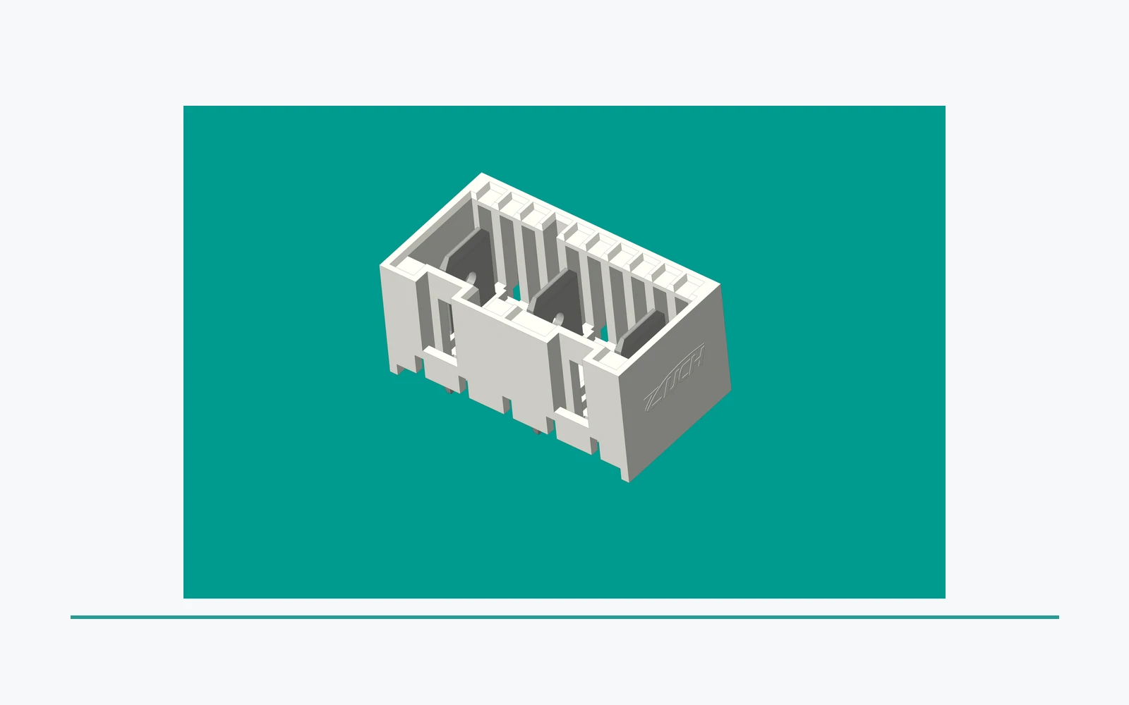
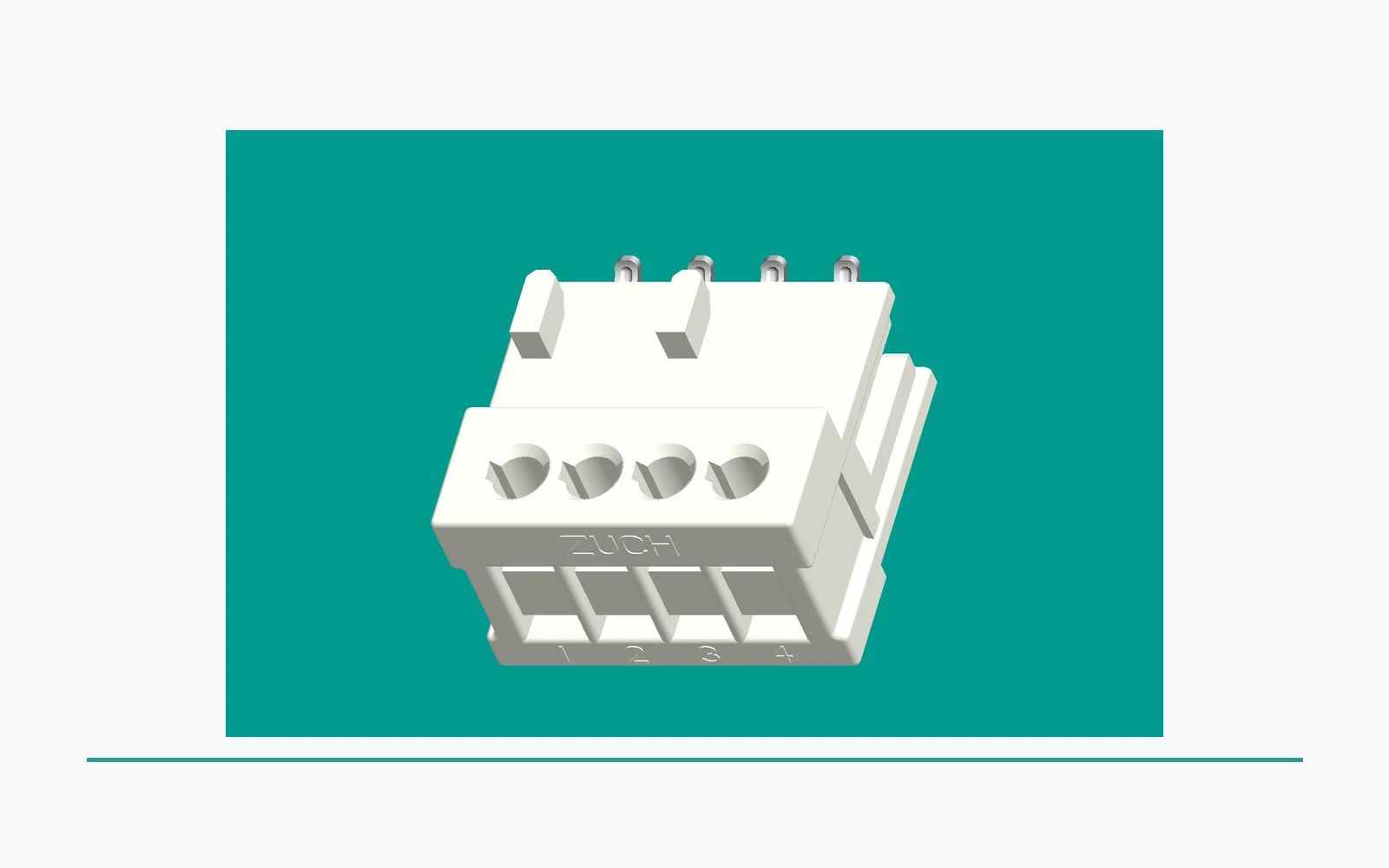
Important: A termination that looks complete in a sample or product image is not evidence that its connector, conductor, tooling, inspection, and application conditions are approved for a finished assembly. Source: IEC 61984 connector overview.
Part 3. Confirm the conductor and connector interface
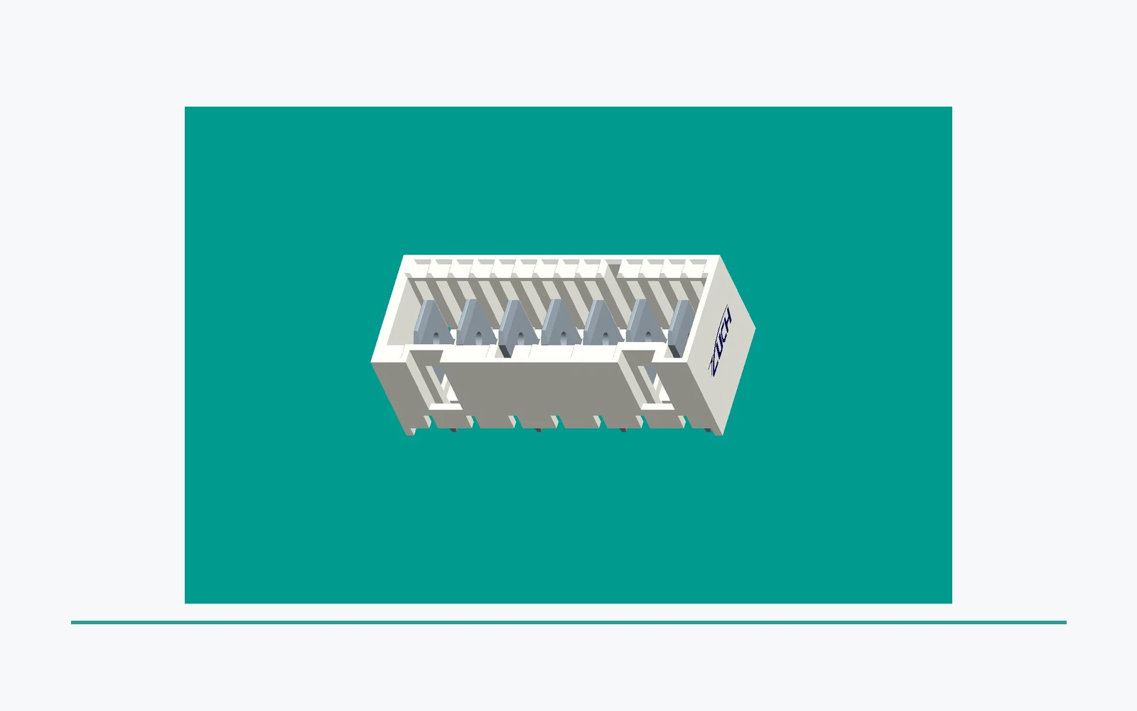
Review the controlled conductor construction, relevant dimensions, connector interface, mating conditions, and any specified strain-relief or routing features. The connector and wire must be assessed as the released system, not as independent catalogue choices.
Retain the drawing revision with the comparison record. This prevents a response for a different wire or connector configuration from being mistaken for a like-for-like alternative.
Part 4. Review assembly, inspection, and service context
Assembly access, routing, cable support, inspection points, and the intended service boundary can affect a termination-system review. Consider the installed assembly rather than an isolated terminal sample.
The organization that owns the product should define its approved assembly and service procedures. This article can identify information to review, but it does not prescribe a production or field sequence.
Part 5. Prepare termination evidence for RFQ
Use a controlled package to request a comparable response. It should state the actual connector and conductor system, not merely ask for an “IDC” or “crimp” option.
| Inquiry item |
Purpose |
Send with RFQ |
| Connector and conductor definition |
Establishes the system being compared |
Current drawings, revision, and wire information |
| Assembly and access conditions |
Identifies installation and inspection constraints |
Routing, support, clearance, and service notes |
| Evidence request |
States program expectations |
Sample objective, requested records, and evaluation needs |
| Change control |
Preserves the approved comparison basis |
Revision, notification, and traceability expectations |
Part 6. Control changes and proposed alternatives
A change to connector geometry, conductor, termination definition, assembly route, tool, inspection condition, or service access can change the original review. Record the difference and route it through the responsible engineering process before relying on prior evidence.
This helps buyers distinguish a controlled alternate proposal from a generic product comparison. The proposed system must be compared with the released configuration.
Part 7. Use ZUCH routes for a controlled RAST connector inquiry
The ZUCH RAST connector family page is a commercial discovery input for a termination-system discussion. It does not confirm an IDC or crimp interface, tooling route, validation, availability, or application approval.
For a termination-system discussion, use the contact page to provide connector and conductor drawings, the termination definition, assembly and access constraints, sample objective, requested evidence, records, and change-control needs. The RAST appliance PCB layout guide covers the related board and routing review.
FAQ
Is IDC always faster than crimp?
Not as a general selection conclusion. Compare the released connector and conductor system, assembly requirements, inspection plan, and evidence needed for the application.
Can IDC and crimp parts be treated as interchangeable?
No. The connector geometry, conductor definition, assembly method, documentation, and required evidence may differ.
What should be compared between termination methods?
Compare the controlled connector and wire system, termination definition, assembly route, inspection conditions, service context, and program evidence.
Why does conductor construction matter?
The termination system must be reviewed against the specified conductor, not an assumed or generic wire description.
Does a visual termination check prove suitability?
No. The responsible program must define the evidence required for the complete controlled configuration.
What should a termination drawing identify?
It should identify the connector and conductor definitions, termination interface, relevant assembly conditions, revision, and related requirements.
What belongs in an IDC versus crimp RFQ?
Provide controlled connector and wire drawings, termination definition, assembly and access limits, sample objective, requested evidence and records, and change-control expectations.
References
 Zhejiang ZUCH Technology Co., Ltd.