Connector Housing Selection: Material, Keying and Retention Features
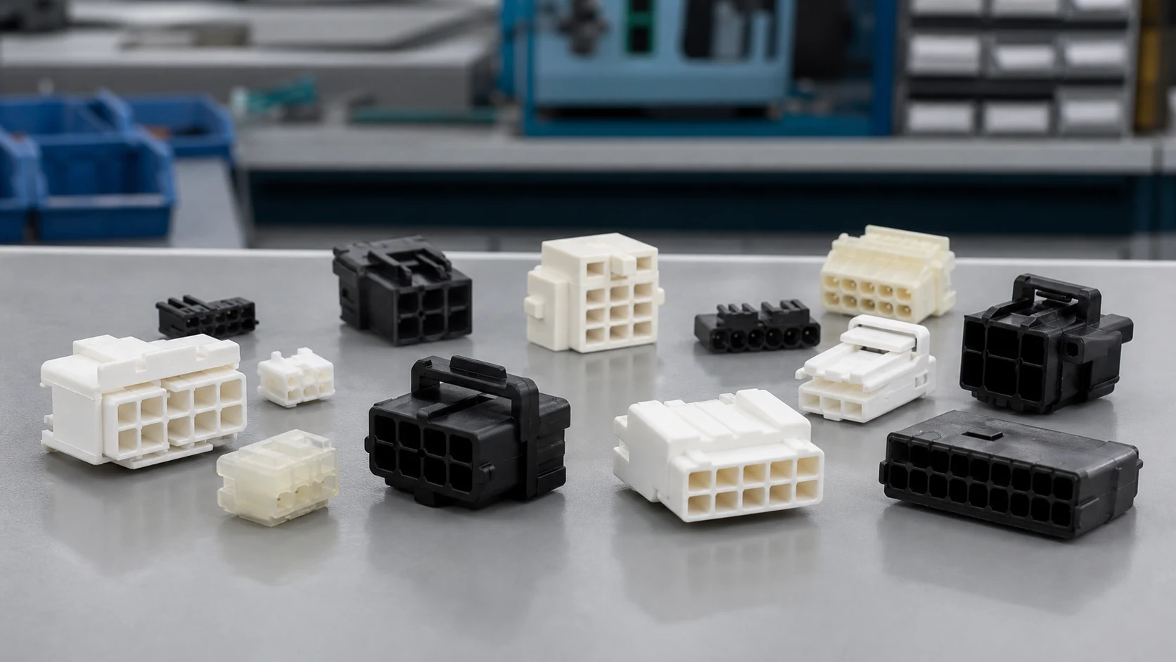
A housing can resemble an existing component and still accept the wrong terminal, permit an unintended mating pair or behave differently after moisture conditioning. For an engineer or buyer replacing a connector, a photograph and cavity count therefore leave important questions unanswered. A fit trial on an empty housing cannot establish terminal retention, and a latch click cannot establish that each contact is seated. These gaps can create assembly rework or an unapproved substitution. This guide explains how to identify the exact component, separate terminal compatibility from counterpart compatibility, and evaluate material, keying and retention evidence before a sourcing decision.
The short answer is that connector housing selection starts with a controlled part number and drawing revision, then evaluates material behaviour, error-proofing features and retention as separate requirements. Confirm the approved terminals, wire combinations and mating counterpart before comparing price. IEC 60512-1:2018 provides a framework for connector tests, but the detail product specification must prescribe the selected tests, severity and permissible limits. This approach applies to new designs and replacement parts alike; a similar appearance or generic polymer name does not establish interchangeability. Next, obtain the component drawings and application instructions, then agree an acceptance plan using the actual assembled configuration.
Inhalt
The housing positions terminals, insulates circuits, carries locking and keying geometry, and shields contacts from handling. Housing fit, retention and damage can affect the assembled connector even when the contact itself is correctly specified. Evaluate these functions together, without treating the housing alone as proof of the complete connector’s electrical rating.
Record the manufacturer, exact ordering part number, drawing revision, cavity arrangement, key variant, colour and required accessories. A photograph is useful for screening visible differences, not for confirming cavity dimensions, resin grade or revision status. Request the drawing’s viewing direction and cavity numbering so a mating-face view is not confused with a wire-entry view.
Why must terminal fit and counterpart fit be checked separately?
Housing-to-terminal compatibility concerns the cavity, contact orientation, retention interface, wire range and any wire seal. Housing-to-counterpart compatibility concerns the mating geometry, key variant, latch, circuit alignment and seals between connector halves. Passing either check does not establish the other. Matching pitch and circuit count is an initial screen, not an approval criterion.
| Interface to verify |
Controlled evidence |
What a visual match cannot establish |
| Housing and terminal |
Approved contact part number, cavity drawing and insertion/application instructions |
Lance engagement, seating or suitability for the actual wire and seal |
| Housing and mating half |
Approved mating part number, keying map, latch and circuit assignment |
Correct contact engagement, cross-mating prevention or sealing |
| Assembly and equipment |
Mounting envelope, harness routing, service access and qualification record |
Acceptable loads or environmental performance in the installation |
Documentation should distinguish component geometry, assembly instructions and product performance. For example, TE Connectivity’s 2415838-1 receptacle contact page separately lists drawing 2415838 Rev A, application specification 114-106638 Rev B and product specification 108-106638 Rev A. This is a documentation example for a wire-crimp contact, not evidence of any ZUCH housing’s rating or compatibility.
| Selection lens |
Questions to close |
Evidence to request |
| Material |
Temperature, moisture, chemicals, flammability |
Compound designation and data with conditioning and test conditions |
| Error-proofing |
Keying options, colours, orientation |
Keying chart and samples of intended and unintended pairs |
| Retention |
Lance type, secondary lock, pull force |
Retention specification and trial results for the defined assembly |
Which material properties matter for the application?
Review temperature range, moisture exposure, chemical contact, flammability class and mechanical toughness against the operating profile. Ask for the specific compound designation rather than a generic polymer family name, because fillers and grades change behaviour. Include reinforcement, relevant stabilizers and any colour-specific evidence needed by the specification.
Should dry material data determine fit in humid service?
Not alone. Polyamide moisture conditioning can change dimensions, stiffness and toughness, so a dry-as-moulded fit trial may not represent the service condition. Define the conditioning state used for dimensional inspection and functional trials, and request the relevant grade data at that state. Polyram’s PBT versus nylon discussion explains these qualitative mechanisms; its generic values are not limits for an unspecified connector compound.
PBT’s lower moisture uptake is not proof that every PBT grade resists hydrolysis during hot wet exposure. Heat or hydrolysis stabilization, reinforcement and other additives matter. Compare the exact grades and the relevant duration, temperature, humidity or chemical exposure rather than choosing a universal material winner. A resin’s flammability result also does not, by itself, approve the complete connector or equipment.
How do keying and polarization prevent different build errors?
Keys, ribs and asymmetric shapes can mechanically block incorrect mating when the intended geometry is present and intact. Polarization controls orientation within the intended pair; keying distinguishes which similar connector variants may pair. Where several similar housings sit near each other, assign documented key options and use colours as an additional identification aid. For a related technical reference, see Nylon vs PBT Connector Housings: How Material Choice Affects Reliability.
Molex’s connector mating fundamentals also distinguishes contact gender from housing form: pin/socket descriptions are not interchangeable with plug/receptacle descriptions. Identify the contact interface and housing type separately. Colour-only coding can guide an operator, but it does not physically stop a wrong pair from mating; a red and a blue housing may remain mechanically compatible.
How should key variants be verified on the assembly line?
Create a pairing matrix for every nearby connector variant, including intended pairs and plausible cross-connections. Verify correct orientation, cavity numbering and electrical circuit mapping separately. Agree controlled wrong-pair trials and acceptance criteria with engineering; do not force production parts together or remove ribs to make a substitute fit. If two variants can cross-mate, record that limitation rather than describing the colour scheme as error-proof.
How do terminal retention and connector locking work together?
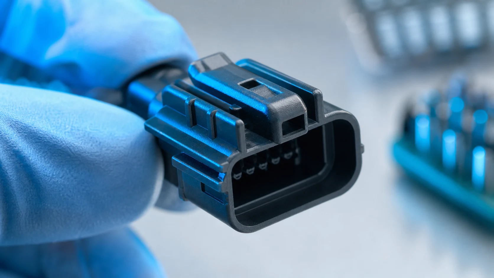
Primary terminal retention comes from the terminal lance or a housing retention feature, depending on the design. Some systems add terminal position assurance (TPA) or another terminal lock. Match the retention system to wire loads and service handling, and verify seated terminals against the specified requirement. Do not assume all devices called secondary locks operate in the same way.
A connector latch retains the two mating halves. Connector position assurance (CPA) acts at that mating interface, while TPA acts on terminals within the housing. Molex’s contact retention guide describes this distinction and shows family-specific TPA implementations. Follow the actual assembly sequence and permitted lock positions; a closed CPA is not a terminal seating check, and a terminal lock does not replace counterpart latch verification.
| Feature |
Purpose |
Verification |
| Polarization rib |
Blocks reversed mating in the specified pair |
Controlled orientation trial with counterpart |
| Terminal lock or TPA |
Controls terminal position or retention as defined by the family |
Specified lock sequence, seating audit and retention check |
| Latch with tactile click |
Indicates latch engagement, not every contact’s seating |
Engagement inspection, assembly trial and service action |
| CPA, where provided |
Restrains release of the mated connector latch as designed |
Full mating and CPA engagement per application instructions |
What should a terminal back-out investigation check?
Check terminal identity and insertion orientation, full lance engagement, housing deformation, lock position and cable strain relief. Distinguish terminal retention in the cavity from wire-to-terminal crimp strength and retention of the mated connector halves. A pull test must identify which interface is being loaded, the sample state and the applicable acceptance limit. There is no universal force value for all housings, and a destructive test should use designated samples rather than release the tested production assembly without an approved disposition.
Which environmental exposures should be stated and tested?
State temperature extremes, humidity, cleaning agents, vibration and any sealing expectation explicitly in the drawing or specification. Sealed families need mating-interface, wire-seal and cavity-plug definitions as a set, not as afterthoughts. Include wire insulation diameter, unused cavities, mating state and accessory identities in the evaluated configuration.
For each exposure, define conditions and duration: operating versus storage temperature, humidity and condensation, chemical identity and concentration, cleaning frequency, vibration profile, harness routing and service cycles. The relevant location is the installed connector, not just the equipment’s advertised ambient condition. Record dimensional fit, latch operation, terminal seating and other required performance checks before and after the agreed conditioning sequence.
The public scope of IEC 60512-11-1:2019, climatic sequence covers a sequence of temperature, humidity and, where required, low air pressure stresses. It does not establish resistance to every cleaning chemical or a service-life guarantee. Under IEC 60512-1:2018, the detail product specification determines selected tests, severity and permissible performance limits. Referencing an IEC method is not certification of a housing.
Wichtig: General guidance cannot approve a specific design or lot. Apply source guidance through a controlled drawing, product specification and acceptance plan; manufacturer examples do not establish ZUCH model performance, compatibility or approval.
What should an RFQ require before a housing or supplier changes?
List the housing part definition, compound, keying option, retention features, mating counterpart and acceptance checks. Add samples and fit trials with the actual terminals and wires, because paper compatibility does not guarantee assembly behaviour. For a related technical reference, see Connector Polarization and Keying: Preventing Mis-Mating in Production.
For a proposed alternative supplier, require a differences register rather than an unsupported statement of equivalence. Compare drawing revisions, cavity and key geometry, resin grade, colour, locking architecture, approved contacts, accessories and mating parts. State whether the proposed assembly is a complete connector system or a mixed-source combination. An alternative housing that accepts the original terminal still needs mating, material and retention evaluation.
How can purchasing prevent an unapproved substitution?
Keep the original part approved until the proposed configuration passes a documented review and the responsible engineering authority accepts it. Agree sample traceability, test conditions, acceptance limits and the evidence needed to close each difference. Require notification and approval for changes affecting the resin, keying, tooling, retention features or component identities. Update the bill of materials and assembly instructions, identify the effective lot or revision, and control old and new inventory so similar-looking variants are not mixed.
The cost comparison for connector housing selection should include any new crimp tooling, inspection gauges, operator training, sample trials and requalification work. A lower piece price is not directly comparable if these costs or acceptance gaps remain unresolved. No specific savings can be calculated without the programme’s actual volumes and validation scope.
Which ZUCH route supports a housing inquiry?
Use ZUCH’s Housing category and the live product catalogue to identify relevant connector, terminal or housing component families. These are discovery routes only and do not demonstrate that a specific configuration is approved for your application.
Which inputs make a housing inquiry actionable?
- Housing part number and drawing revision with compound, keying option and colour.
- Terminal and wire combinations with separate terminal, crimp and mating retention requirements.
- Environmental exposures, conditioning state, sealing needs and exact mating counterpart.
- Traceable samples, fit-trial plan, change-control requirements and acceptance records expected.
What remains outside a catalogue-based selection?
This guide supports engineering and sourcing discussion; it cannot replace programme-specific validation, market requirements, or an approval record. Use ZUCH’s sample request route or contact page for controlled component documentation and samples. A supplier response should close the exact model’s evidence gaps rather than rely on a company-wide certification statement.

Frequently asked questions
What does a connector housing actually do?
It positions and insulates terminals, provides locking and keying geometry, and protects contacts during handling. It is one component of the connector system, so its identity alone does not establish the complete assembly’s rating or suitability.
How do I choose a housing material?
Match compound-level data to temperature, moisture, chemical, flammability and toughness requirements from the operating profile. Request the test and conditioning state behind the data; dry polyamide properties may not represent conditioned service, and low PBT moisture uptake does not prove hot-wet durability.
What is the purpose of housing keying options?
Distinct mechanical keys restrict which similar connector variants can mate. Verify the allowed and prohibited pairs using the manufacturer’s keying map and a controlled trial. Colour-only coding is a visual aid, not a physical barrier.
What is a secondary lock in a housing?
The term is incomplete without identifying the interface. A terminal lock or TPA addresses terminals inside the housing according to the family design; a CPA addresses the mated connector latch. Obtain the assembly instructions before assuming what a closed lock confirms.
How is terminal retention verified?
Use seating audits and specified retention checks with the actual terminal, housing and wire combination. Define the loaded interface, lock state, conditioning and product-specific acceptance limit. A crimp pull test measures a different interface and cannot substitute for cavity retention evidence.
Do sealed housings need special definition?
Yes. Interface seals, wire seals and cavity plugs must be specified together and validated as a system. Include the actual wire insulation diameter, unused positions and mating state; a housing described as sealed is not evidence for every assembled configuration.
What belongs in a connector housing RFQ?
Include exact component identities and revisions, compound definition, keying, retention, environmental conditions, counterpart, samples and acceptance checks. For substitutions, also require a differences register, traceability and written change acceptance before production release.
Can a same-pitch housing from another supplier be used as a replacement?
Not on pitch alone. Terminal fit, mating geometry, keying, locking, material and environmental performance need separate review for the proposed configuration. Keep the replacement unapproved until the programme’s engineering authority accepts the documented evidence and updates controlled records.
References
Public sources checked on 10 October 2026. IEC catalogue summaries establish scope, not the full normative procedures or acceptance limits; manufacturer editorials explain mechanisms, not ZUCH model qualification.
When is a housing ready for approval?
A housing is ready for approval when its identity and evidence match the intended assembly, not when it merely resembles the existing part. Begin connector housing selection with exact component numbers and revisions, then confirm the terminal interface and mating interface independently. Evaluate the named resin grade under relevant conditioning and exposure, and verify keying, terminal locks and connector latches for their distinct functions. Do not skip a controlled acceptance record because a sample fits or a colour code looks familiar. If an alternative supplier introduces a difference, keep that difference open until engineering accepts the supporting trials and updates production records. ZUCH’s housing and product categories provide a starting point for identifying candidate families; use the linked sample or contact routes to request the model-specific drawings and documentation needed for the next review.
 Zhejiang ZUCH Technology Co., Ltd.