Plug vs Receptacle Connectors: A Design Guide for Mating Interfaces
A buyer can order a “receptacle” and still receive the wrong half of a connector system. The term may describe the housing’s mating role, a female socket contact, or a fixed mounting position, depending on the catalogue field and product family. A crimp receptacle contact, for example, is not by itself a panel receptacle. Confusing those descriptions can send the wrong terminal to harness assembly or reverse a pin assignment when two mating-face drawings are compared. Plug vs receptacle connectors therefore cannot be chosen from a male/female label alone. The useful decision is to identify the physical pair, the source side, the installed mounting and the viewing direction of the contact map before approving either part number.
The short answer is that a plug and a receptacle name mating-interface or housing roles; male and female name contact geometry, while cable, panel and PCB name termination or mounting arrangements. In many assemblies the plug is the handled half and the receptacle is fixed, but this convention does not determine which one contains pins or remains energized. Molex’s connector-mating guide explicitly separates contact gender from housing type and shows both plug housings with female terminals and receptacle housings with male terminals. For a real selection, obtain the family drawing for both halves, confirm the mating view and pin numbering, then verify the approved contact, termination and application-specific acceptance conditions.
Inhalt
What defines a plug and a receptacle in a mating pair?
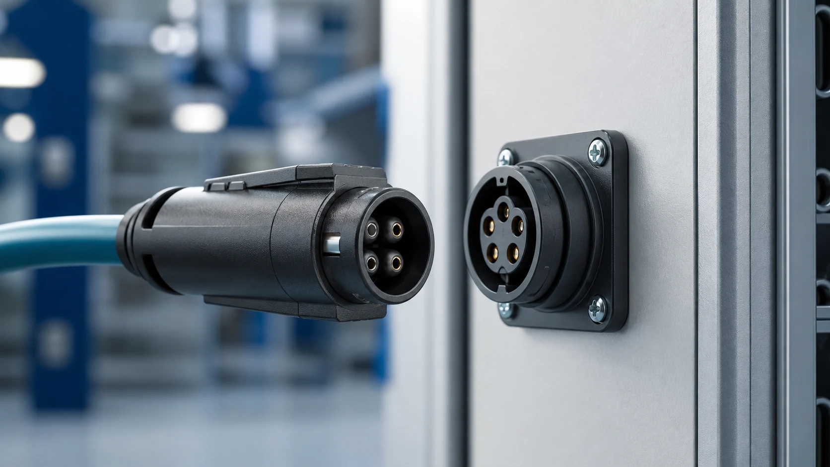
The plug is conventionally the free or moving half that enters, and the receptacle is the fixed half that receives it. Those are useful descriptions of a particular assembly, not a rule that converts “plug” into male or “receptacle” into female. Contact gender can vary independently of that convention, so drawings should state both the housing role and the contact gender explicitly. Molex’s Connector Fundamentals: Gender, Polarization, Keying and Coding gives manufacturer examples of the reverse combinations and of genderless mating systems.
| Role element |
Plug half |
Receptacle half |
| Motion in a common arrangement |
Free or cable side, moves in service |
Fixed to panel, board or enclosure |
| Typical exposure |
Handled by operators |
Position and tolerance controlled |
| Documentation to check |
Cable exit, strain relief, grip; actual contact type |
Mounting, sealing, fixing hardware; actual contact type |
The table compares common handling roles, not interchangeable part specifications. TE Connectivity, for instance, lists part 2415838-1 as a receptacle contact with a crimp termination to wire and cable. Here “receptacle” identifies the contact type; its product drawing and matching housing documentation must establish the assembled connector configuration. It neither sets a ZUCH rating nor implies that every receptacle is board-mounted.
A widely used practice keeps the side that remains energized on recessed contacts, so an unmated live half is less accessible to touch or short. Molex describes this as a typical safety consideration, while also noting that a free-hanging harness may benefit from protected socket contacts during handling. Those considerations can point to different sides. Apply the rule through the system safety review of sources, stored energy, accessible conductive parts and service procedures rather than by assuming the fixed half is always live. A recessed contact alone is not evidence that the complete unmated assembly satisfies a touch-protection requirement.
Before locking a gender assignment, mark which side may be energized at every disconnect state. Then review exposed-pin damage risk and physical guarding in the installed location. The chosen family must offer mating contacts and a housing arrangement that actually implement that decision; a catalogue label cannot substitute for the drawing and safety assessment.
How do panel, cable and board mounting change the choice?
Receptacles often mount to panels or boards where position is controlled, while plugs terminate the cable that moves during service. Mounting style drives sealing interfaces, strain relief, fixing hardware and the tolerance chain to the mating half. Yet “receptacle contact” may be a crimped part on a cable, and a board-mounted header can use pin or socket contacts. Keep three separate fields in the interface record: housing or mating role, contact type, and attachment or termination method.
For a panel pass-through, inspect the family drawing for panel cut-out, fastening, orientation and any specified sealing components. For a PCB connection, check the actual header footprint, assembly process and the cable exit relative to nearby hardware. For a moving harness, define bend routing and strain relief so the terminals and latch do not carry unsupported cable loads. None of these arrangements follows automatically from the word “plug.”
How do mating view, pin assignment and keying interact?
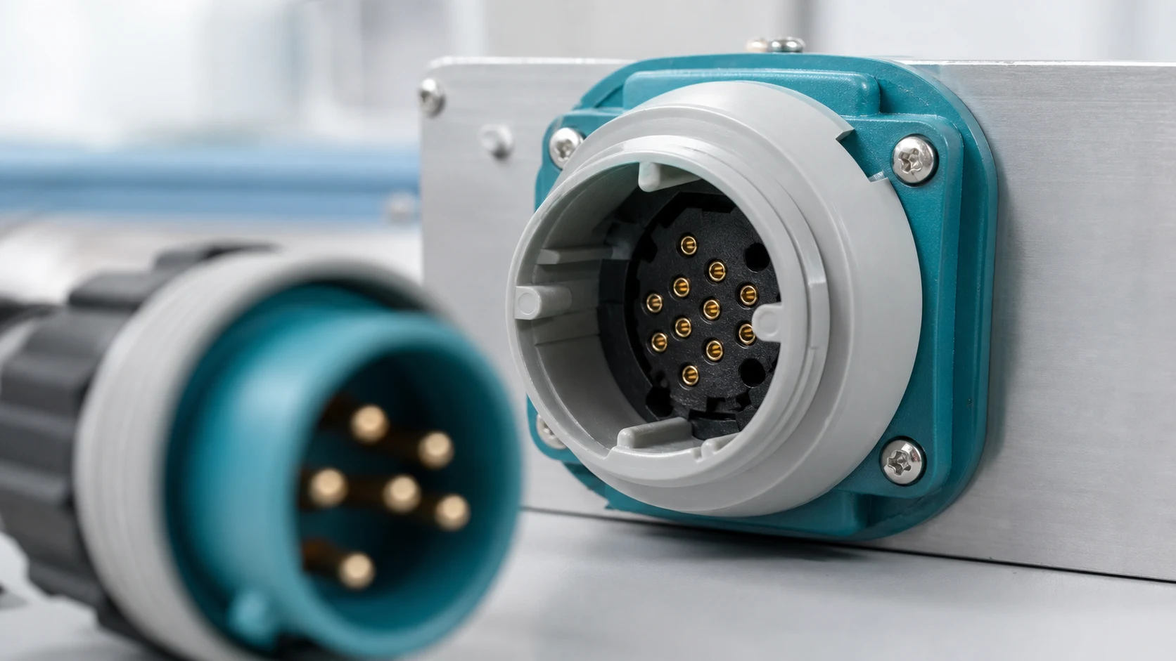
Polarization geometry must exist in the matching interface and remain effective in the installed orientation, including blind-mating situations. Where similar pairs sit side by side, assign distinct available keys and record the assignment in the drawing set; colours can assist identification but are not a physical barrier unless the family uses a corresponding mechanical code. Harwin’s What are Polarization and Keying in Connectors? distinguishes orientation control within a pair from wrong-pair rejection among similar connectors.
Pin assignment is another independent layer. Label each drawing “mating face” or “wire/termination side,” show the key or latch at the same reference position, and copy the manufacturer’s cavity numbers rather than inferring them from left-to-right appearance. Opposing mating faces appear mirrored when viewed straight on. Confirm the resulting continuity map on a representative mated pair, including power and return, before releasing harness and PCB drawings. A correctly polarized pair can still be electrically miswired if the view or numbering convention is reversed.
| Load case |
Design response |
Verification |
| Cable weight and pulls |
Strain relief on the cable side |
Pull check on representative build to agreed limits |
| Misaligned mating |
Family-specified lead-in or float features, if available |
Mating trial at installation tolerance extremes |
| Vibration |
Specified latch or coupling and cable support |
Retention check under the application load profile |
What mechanical loads should the interface tolerate?
Consider mating misalignment, cable weight, service pulls and vibration transmitted through the mounted half. Decide where strain relief and support act, and confirm latch or coupling strength against the load path actually expected. The second table turns each likely disturbance into a build-level check, but it supplies no universal pull-force or cycle-life limit. Repeated service also makes grip access and the manufacturer’s allowed unmating method relevant, since pulling on conductors can load terminals even when the latch is suitable.
Wichtig: General guidance cannot approve a specific design or lot. IEC 60512-1:2018 describes a framework for connector tests and measurements; the detail product specification selects tests, severity and permissible limits. It does not certify this or any particular mating pair by itself. Apply the relevant family specification through a controlled drawing and acceptance plan.
How should the mating interface be documented?
Document both halves, contact gender, keying, sealing, mounting and the mated-pair acceptance checks in one interface definition. Sourcing then evaluates alternatives against the pair, which prevents a compatible-looking half from breaking the system. Include exact housing and contact part numbers, wire size and termination tooling where applicable, drawing revisions, the keyed orientation, and pin assignment from explicitly named views. The approval record should map each cavity on one side to its actual mating counterpart, not merely repeat two independent numbering diagrams.
The document stack is family-specific. TE’s 2415838-1 contact listing separates product drawing 2415838 Rev A, application specification 114-106638 Rev B and product specification 108-106638 Rev A. Those are examples of document types to request for the selected family, not transferable requirements or proof of cross-brand compatibility. The public catalogue for IEC 60512-1:2018, edition 5.0 likewise says detail specifications prescribe test selection, severity and permissible limits. Confirm the applicable revision and acceptance owner before committing to tests or an alternate source.
What should a mating-pair inquiry include?
Use ZUCH’s Plug Housing category and the live product catalogue to identify relevant connector, terminal or housing component families. These are discovery routes only and do not demonstrate that a specific configuration is approved for an application. In a plug vs receptacle connectors inquiry, identify the complete mating pair and ask for its own controlled drawings and specifications.
Which details belong in an RFQ?
- Interface definition naming both halves, housing roles, contact genders, part numbers and termination method.
- Mounting, sealing, cable routing and strain-relief requirements per half; unmated exposure and source state.
- Keying assignments, mating-face orientation, cavity numbering and the mapped electrical pinout.
- Mated-pair acceptance checks, application load cases, current drawing revisions, samples and records expected.
Where does the fit decision stop?
This guide supports engineering and sourcing discussion; it cannot replace programme-specific validation, market requirements, or an approval record. Use ZUCH’s sample request route or contact page for controlled component documentation and samples.

FAQ
What is the difference between a plug connector and a receptacle connector?
They identify complementary mating or housing roles in a named family. In a common installation the plug is handled and the receptacle is fixed, but the actual contact genders and mounting arrangements must be read from that family’s drawings.
Is a plug connector typically male or female?
Neither gender is guaranteed by “plug.” It can house pin or socket contacts; specify the mating contact type explicitly, then check that the complementary half and terminal are listed for the family.
Are receptacles male or female?
A receptacle contact is a female socket in many product catalogues, whereas a receptacle housing can carry male pins in some systems. The exact noun and product field matter: TE’s wire-crimp receptacle contact is a contact, not proof of a panel-mounted female connector.
Should the live side be the plug or the receptacle?
The safer contact exposure depends on which half may remain energized when unmated, not its role label. Recessed or otherwise guarded live contacts are a common starting point, subject to a system-level touch and fault review.
How do I stop two similar pairs from being cross-mated?
Choose available distinct mechanical key options, confirm wrong-pair rejection on the assembled installation, and use colour only as a supplementary cue. For a related board-level distinction, see Pin Header vs Socket Header: When Each Board Connection Makes Sense.
Which half should get strain relief?
The cable side normally needs cable support, whether the supplier names that assembly a plug or a receptacle. Route the cable and check service pulls so the contact and latch do not carry the unsupported load.
What checks prove a mating pair is acceptable?
The approved plan may include pin-map continuity, proper mating and wrong-key rejection, contact retention, relevant electrical checks and any application sealing or mechanical trials. Methods and limits come from the selected family specification and the installation requirements, not from a generic checklist.
What should a plug and receptacle RFQ define?
Name both parts and revisions, roles, contact genders, mounting and terminations, keyed mating-face views and cavity-to-cavity pinout. Include the disconnect source state, load cases, samples and required mated-pair acceptance evidence.
References
How should the final pair be chosen?
For plug vs receptacle connectors, the decisive distinction is not a simple male/female conversion: housing role, contact geometry and mounting describe different aspects of the same interface. First identify both mating halves and the unmated source state; next define the cable, panel or board installation and choose contact protection and keying for that arrangement. Then reconcile the two pin maps from their stated views and confirm the cavity-to-cavity connections on samples. Do not skip the family drawing, application specification or the agreed tests because two parts appear to fit. General connector test frameworks leave test selection and limits to the detail specification. ZUCH’s catalogue is a starting point for a mating-pair inquiry; request the matching drawings and samples through the existing product and contact routes before approving a configuration.
 Zhejiang ZUCH Technology Co., Ltd.