Rectangular Connector Locking: Compare Lever, Screw, and Clip Interfaces
When a plant engineer in Suzhou encountered a replacement-connector problem, she specified a rectangular sample and saw it mate but fail to release with the installed cover in place; the reversal was that the interface selection and access envelope—not a supposedly bad connector—caused the failure. A lever, screw, or clip lock must therefore be reviewed against the released mating definition, assembly access, retention evidence, and service process. IEC 61984 frames connector safety and performance around the complete interface, so the practical action is to compare the documented mechanism and installation conditions before approving an alternate.
Contents
Define what the locking mechanism must control
A locking feature is part of a connector system. The review starts with the controlled housing, mating part, keying, cable or board orientation, enclosure, and access conditions that define the intended assembly.
This prevents procurement from treating a mechanism label as a universal performance category. The actual design determines what must be retained, how it is mated, and how it can be inspected or serviced.
| Review question |
Why it matters |
Controlled input |
| What must mate together? |
Identifies the exact interface relationship |
Connector and mating-part drawings |
| What access is available? |
Shows whether the mechanism can be assembled or released as intended |
Enclosure, harness, and tool-clearance layout |
| What evidence is required? |
Separates a supplier discussion from an approved design |
Program evaluation plan and release criteria |
Compare lever, screw, and clip interfaces
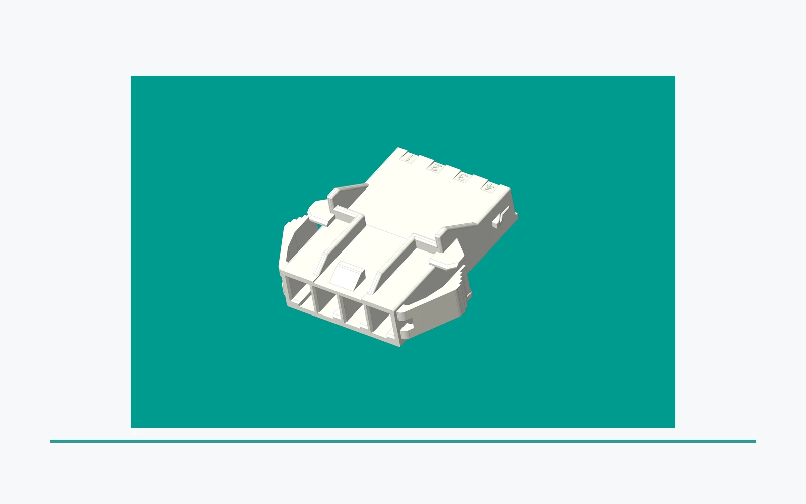
Lever, screw, and clip mechanisms may differ in actuation method, required clearance, visual confirmation, and service process. Compare only the features shown on the released connector and mating definition; do not infer that every product using a label has the same geometry or retention behavior.
A lever concept may need an actuation path, a screw interface may depend on specified hardware and controlled installation conditions, and a clip interface may depend on its defined latch relationship. Those are review prompts, not performance conclusions.
Comparison matrix: The entries below describe questions to close with the connector and hood/housing documentation. They are not universal rankings; the released product definition controls the answer.
| Review dimension |
Lever interface |
Screw interface |
Clip-style interface |
| Mating effort |
Assess lever travel and hand clearance; use released instructions. |
Assess seating effort plus any specified tightening step. |
Assess insertion force and tactile or audible engagement defined by the supplier. |
| Tools |
Usually reviewed as a hand-actuation question; confirm any tool prohibition or requirement. |
Confirm driver type, bit access, and documented torque. Never invent a torque value. |
Confirm whether the defined latch can be engaged and released by hand or needs a specified aid. |
| Installation access |
Reserve the full lever sweep and a line of sight for final position. |
Reserve axial and radial driver access, plus space to verify the fastener. |
Reserve the insertion and release path; covers may hide the latch. |
| Retention verification |
Check both levers in the documented locked position and any visual indicator. |
Check seating, fastener position, and the applicable installation record. |
Check complete latch engagement, flushness, and the specified release check. |
| Maintenance frequency |
Set inspection frequency from the equipment maintenance plan and supplier instructions. |
Set inspection or re-tightening only where the equipment and connector documentation require it. |
Set inspection for wear or latch damage from the service plan; do not assume a cycle life. |
| Declared environmental limits |
Use the selected hood/housing datasheet for temperature, ingress, corrosion, and other declared limits. |
Use the selected hood/housing and hardware documentation; the screw label supplies no universal limit. |
Use the selected housing and clip documentation; do not transfer limits from another series. |
There is no universal vibration ranking for lever, screw, or clip interfaces. Vibration suitability depends on the complete connector, housing, mounting, cable support, mating condition, and the application test or specification that governs the project.
Important: A connector mechanism that looks retained in a drawing or catalogue view is not evidence of suitability for vibration, load, or service use in a finished product. Source: IEC 61984 connector overview.
Verify the mating and retention definition
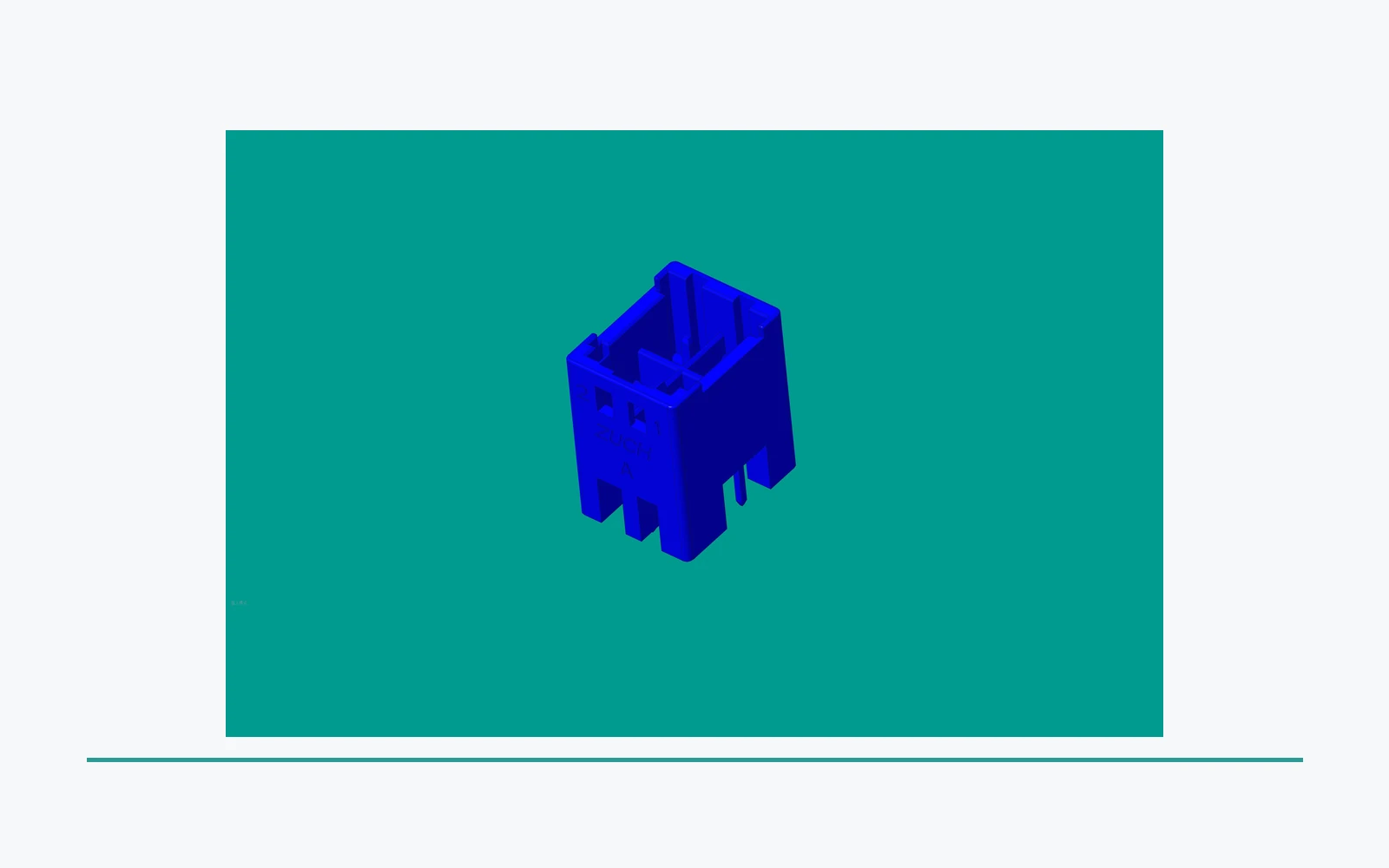
Review the controlled mating direction, keying, polarization, locking engagement, nearby obstructions, and any specified inspection condition. The same lock style can produce different outcomes when the mating housing, terminal system, or packaging changes.
Keep the review tied to a specific drawing revision. This gives the project team a reliable basis for comparing samples or responses against the intended interface.
Locked-state inspection points
- Confirm the connector is fully seated against the mating face with no visible gap beyond the released drawing allowance.
- Confirm every lever is in the documented locked position, each screw head or captive fastener is seated, or each clip is fully engaged.
- Check keying and polarization before applying any retention force; do not use the lock to pull a misaligned connector into place.
- Verify that the cable, cover, and adjacent hardware do not push the mechanism toward release or block the required inspection view.
- Record the drawing revision, mechanism state, inspector, and any measured torque only when that torque is specified in the applicable connector or equipment documentation.
Review assembly and service access
Access determines whether a mechanism can be mated, visually checked, released, or replaced within the intended assembly. Consider harness routing, covers, adjacent components, tooling space, orientation, and the conditions the service organization controls.
Service access should remain part of the released design review. An article cannot prescribe an assembly sequence or determine whether a worker may service particular equipment.
Build the locking-mechanism inquiry record
Send a controlled package instead of a broad request for a “locking connector.” The table below makes the inputs visible to both engineering and sourcing.
| Inquiry item |
Why it is needed |
Send with RFQ |
| Mating and lock definition |
Defines the interface to be compared |
Current connector, mating, and keying drawings |
| Envelope and access |
Identifies actuation, inspection, and service limits |
Layout, harness route, clearance, and orientation notes |
| Evidence request |
States what the project needs to review |
Sample objective, records, and evaluation expectations |
| Change control |
Preserves the approved comparison basis |
Revision, notification, and traceability expectations |
Control changes and proposed alternates
A new lock style, mating housing, keying feature, terminal system, enclosure, or harness route can change the interface review. Treat the proposal as a documented change rather than relying on a generic retention label.
Compare alternates against the same released revision. The responsible engineering team can then determine whether the proposal needs updated drawings, samples, evaluation, or release evidence. For the related packaging tradeoff, review the rectangular connector pin-count guide with the same controlled-interface discipline. For a related technical reference, see RAST Connector Termination: Compare IDC and Crimp Interfaces by System. For a related technical reference, see Quick-Connector vs Permanent Crimp: Compare the Complete Interface System.
Use ZUCH routes for a controlled connector discussion
ZUCH’s rectangular connectors route and product catalogue provide a commercial starting point for identifying connector families. They do not prove that a particular lock mechanism meets an application requirement.
For an inquiry, include the controlled drawings, mating and lock definition, access envelope, routing constraints, sample objective, requested records, and change-notice expectations. Submit the package through the sample request route or contact page.

FAQ
Should I choose lever locking, screw locking or a clip-style interface for equipment exposed to vibration?
There is no universal vibration ranking. Choose the interface whose complete connector, hood or housing, mounting, cable support, and documented application evaluation match the equipment; a mechanism label alone cannot establish suitability.
Which locking system is easiest to install and service when access is restricted?
The easiest system is the one that fits the available actuation, inspection, and release path in the released layout. Compare lever sweep, driver access, clip engagement visibility, service tooling, and the supplier’s instructions before deciding.
What should be compared between locking mechanisms?
Compare the controlled mating interface, keying, actuation path, access, inspection condition, service need, and evidence expected by the program.
Why does service access matter?
It affects whether the connection can be inspected, released, or replaced within the installed assembly and approved service process.
Does a latch feature prove vibration suitability?
No. Suitability depends on the complete released connection and application-specific evaluation.
What should the drawing identify?
It should identify the connector and mating relationship, keying, locking definition, relevant dimensions, access constraints, and revision.
What belongs in a locking-mechanism RFQ?
Provide controlled connector and mating drawings, lock and keying details, access limits, sample objective, requested evidence, and change-control requirements.
References
Conclusion
A rectangular connector locking decision is a controlled interface decision. Lever, screw, and clip mechanisms each change the actuation path, access envelope, inspection method, and service record, while the selected hood or housing establishes the environmental limits that can actually be declared. Use the released mating drawings, supplier instructions, and application evidence as the comparison baseline; never transfer a torque value, vibration claim, maintenance interval, or temperature limit from another series. In restricted spaces, verify the complete locked state before closing covers and record the drawing revision used for acceptance. ZUCH can help structure an inquiry around those inputs through its rectangular connector route, catalogue, sample request, and contact channels. The dependable outcome comes from documented fit and verification, not from assuming one lock style is universally best.
 Zhejiang ZUCH Technology Co., Ltd.