Zhejiang ZUCH Technology Co., Ltd.
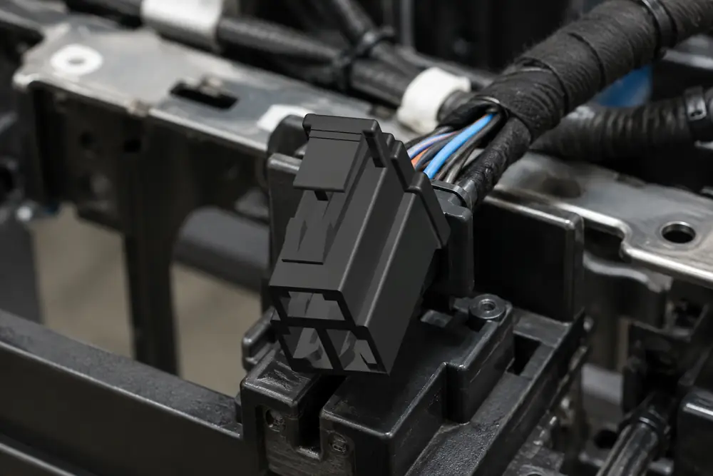
When a component engineer in Nagoya compared terminals after a durability build, the apparently better-conducting option relaxed under repeated mating; the contact interface became less consistent sooner than the team expected. The reversal was important: the root cause was not a defective connector, but an incomplete selection that considered conductivity without weighing spring force, material temper, contact geometry, and the plating system.
Summary: Copper alloy and brass each have a place in connector contacts, but neither label alone predicts service performance. SAE USCAR-2 and IEC 61984 address connector-system performance or safety considerations within their respective scopes, rather than validating a single material property. Specify the alloy family, temper, geometry, plating, mating conditions, and environment together; then confirm the proposed design with application-relevant qualification evidence.
Contact material choices matter because a terminal must carry current while maintaining a stable mechanical interface over handling, mating, vibration, and environmental exposure. A useful starting point is to distinguish electrical conductivity from the contact force that helps manage the interface.
Copper alloy and brass solve different parts of the contact problem
“Copper alloy” is a broad engineering category, not a single grade. Copper may be alloyed to balance conductivity, strength, stress-relaxation resistance, formability, or other properties relevant to stamped and formed contacts. Brass is itself a copper-zinc alloy family, commonly valued for workable processing and a practical balance of electrical and mechanical behavior. The decisive question is therefore not whether copper alloy or brass is universally better, but whether a defined grade in a defined temper supports the terminal design and duty cycle.
A higher-conductivity base material can reduce bulk resistance through the terminal, but that benefit does not guarantee a more durable electrical interface. The mating zone depends on normal force, surface finish, geometry, and the condition of the opposing contact. Conversely, a material selected for spring behavior may support force retention in a compliant beam, while needing a different cross-section or plating approach to meet the electrical and environmental requirements.
| Selection dimension | Copper-alloy contact approach | Brass contact approach | What to verify |
|---|---|---|---|
| Electrical path | May be chosen where the specified alloy supports the required conductivity and terminal layout. | May provide a workable electrical path when sized for the circuit and terminal design. | Voltage drop, temperature rise, and contact resistance under the applicable test plan. |
| Spring behavior | Some alloy families are selected to support resilient contact geometries and force retention. | Suitability depends on grade, temper, beam shape, and the expected deflection. | Insertion/extraction force and force retention after the relevant conditioning. |
| Manufacturing | Forming response varies substantially by grade and temper. | Often considered for its formability, subject to the chosen grade and process window. | Stamping trials, burr control, bend radii, and plating coverage. |
| Corrosion strategy | Base material must be assessed with its plating and intended atmosphere. | Base material must be assessed with its plating and intended atmosphere. | Mixed-metal pair, fretting exposure, humidity, and contaminant conditions. |
| Total-cost logic | May justify process or material cost when it reduces design risk in the intended duty. | May support economical production where the design and qualification requirements align. | Scrap, tooling life, assembly yield, validation scope, and field-service consequences. |
Conductivity, spring force, and geometry must be selected as a system
Contact resistance at a mated interface is not simply the resistivity of the strip material. Real contact occurs at microscopic asperities under normal force. A terminal that begins with acceptable electrical measurements can still become marginal if relaxation, wear, vibration, contamination, or insufficient plating integrity changes that interface. This is why test plans commonly combine electrical checks with mechanical cycling and environmental conditioning rather than treating conductivity as a stand-alone pass criterion.
Geometry is a practical lever. Beam length, material thickness, formed profile, engagement path, and contact-point location influence deflection and force. Temper is equally consequential: it describes a condition of the material that affects how the formed terminal behaves. Changing a grade or temper without revisiting the beam calculation and validation plan can create a hidden substitution risk, even when the part looks identical in a drawing review.
The same logic applies to automotive electrical connector designs. Vehicle vibration, heat, moisture, fluids, and repeated service operations can make an apparently small material decision consequential. A sourcing specification should identify the permitted material condition, the interface plating, the mating half, and the validation evidence required for the actual circuit and environment—not only a generic material name.
Plating is part of the electrical interface
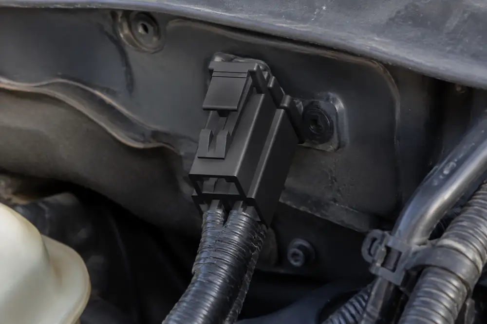
Gold and tin are not interchangeable labels for “good plating.” Their suitability depends on factors including mating system, contact force, expected motion, current regime, temperature, storage, and corrosion exposure. Plating thickness, underlayers, porosity control, coverage around formed features, and compatibility with the mating contact also affect results. Treat the base metal and plating as one engineered stack, and ask whether the supplier’s process controls address the formed terminal rather than only flat coupon material.
For related repair considerations, including diagnosis before a terminal is replaced, consult this guide to automotive electrical connector repair. Repair practice should preserve the terminal system’s intended crimp, retention, sealing, and interface conditions.
Use application conditions to make the material decision
| Application situation | Primary decision focus | Material-system questions | Useful evaluation route |
|---|---|---|---|
| Protected, low-motion signal interface | Stable interface and manufacturability | What normal force and plating are appropriate for the mating system? | Baseline electrical, mechanical, and storage conditioning checks. |
| Frequently mated service connector | Wear and force retention | Will the selected temper and beam geometry retain usable force through the required cycles? | Mating-cycle and insertion/extraction-force testing with electrical checks. |
| Power or higher-current terminal | Thermal and conductive path design | Does the contact cross-section, alloy, crimp, and interface meet the circuit design intent? | Application-specific temperature-rise and voltage-drop evaluation. |
| Exposed automotive environment | Corrosion, vibration, sealing, and fretting risk | How do plating, mating material, seal design, and contaminants interact? | Combined environmental and mechanical validation relevant to the installation. |
This matrix is a decision aid, not a substitute for qualification. In particular, the phrase automotive electrical connector types covers diverse connector architectures; a material decision for one family should not be copied to another without checking geometry, current path, mating half, and service exposure. The cost comparison should include more than strip price: tool wear, plating process capability, inspection, validation, warranty exposure, and downtime may all affect total cost of ownership.
Standards, documentation, and a disciplined selection guide
Standards help turn material assumptions into repeatable evidence. SAE USCAR-2 addresses performance expectations and test methods for automotive electrical connector systems; it is not a blanket certification for every connector. IEC 61984 addresses safety requirements and tests for connectors within its stated scope, while NIST’s Physical Measurement Laboratory provides broader measurement-science context rather than product approval.
Applicable requirements depend on destination market, intended use, customer specification, and the claims made in product literature. Calling a part “compliant” without tying that claim to the correct scope, configuration, test evidence, and control of change can create commercial and quality risk. A test method describes how a characteristic may be evaluated; it does not by itself certify every material, plating variant, or assembled connector.
For procurement, the practical sequence is concise:
- Define the circuit, mating count, environment, terminal geometry, and acceptable change-control boundaries.
- Request the exact alloy designation or approved family, temper, plating stack, mating-contact specification, and process documentation.
- Map the requested validation to the actual connector system, including crimp, housing, seal, cable, and mating half where relevant.
- Review substitutions for their effect on force, plating adhesion, dimensions, electrical interface, and required requalification.
When developing automotive pin connectors or related assemblies, ZUCH can be consulted as a selection guide for configurable connector options and documentation discussions. Buyers should still align final material and validation requirements with their own application specification and applicable customer standards. For standards context, this overview of automotive connector standards is a useful companion.
Frequently asked questions
Are copper alloy contacts better than brass contacts?
Neither is automatically better. The better choice is the specified alloy and temper that support the required conductivity, contact force, geometry, plating system, and environment. Compare the complete contact system against its intended validation plan.
Which connector contact material has better conductivity?
Conductivity varies by the exact alloy, not simply by the broad label “copper alloy” or “brass.” It should be evaluated with the terminal cross-section and interface resistance, because the mated contact performance also depends on force and surface condition. For a related technical reference, see How Contact Resistance Affects Connector Performance.
Why is brass used in electrical connector terminals?
Brass can offer a useful balance of electrical behavior, formability, and manufacturability for suitable connector designs. Whether it is appropriate depends on the selected grade, temper, terminal geometry, plating, circuit requirement, and service environment.
How does contact material affect spring force?
Material family and temper influence how a formed contact beam responds to deflection and how it may change during service. Beam geometry, thickness, forming quality, and operating conditions also matter, so force should be verified on the finished terminal rather than inferred from a material label.
Does gold or tin plating matter more than the base metal?
Both matter because they perform different functions in one interface. Plating governs the surface interaction, while the base material and temper help determine the supporting contact mechanics; select the stack together and verify it with the intended mating half.
Which contact material is best for corrosive automotive environments?
There is no universal best material for every corrosive automotive environment. Assess the exact contaminants, moisture, temperature, vibration, seal design, mating material, plating stack, and validation scope; the relevant environmental tests should represent the installation rather than a generic label.
References and the sourcing decision
- SAE International, USCAR-2 Performance Specification for Automotive Electrical Connector Systems.
- International Electrotechnical Commission, IEC 61984 connector safety requirements and tests.
- National Institute of Standards and Technology, Physical Measurement Laboratory.
Choose the contact material the way you choose the connector: as a complete interface under real conditions, not as a single attractive property on a datasheet.
At the point of sourcing, review ZUCH options with the circuit, environment, material specification, and validation record in hand. Explore the relevant connector products and contact the team to discuss a configuration aligned with your application.