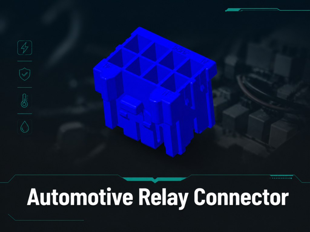
Automotive Relay Connector
There are many components that comprise the backbone of an automotive electrical system, but one that is often overlooked is the automotive relay connector. Automotive relay connectors are essential to provide a secure and efficient connection between the automotive relay and its corresponding automotive wiring system. This article will provide relevant information about the types, significance, and application of automotive relay connectors so that you may fully appreciate the importance of automotive relay connectors in our modern vehicle systems.
What is an Automotive Relay Connector?
An automotive relay connector is a specialized device that provides a secure mechanical mounting for the relay and connects the relay to the electrical circuit. An automotive relay connector, therefore, is critical in providing a reliable source of electrical energy for various automotive systems, such as headlights, fuel pumps, and cooling fans. If an automotive relay connector is of poor quality, a poor electrical connection may occur, which could cause a failure of the system, resulting in less performance and in some cases, unsafe conditions.
Types of Automotive Relay Connectors
However, there are differences between the various types of automotive relay connectors. A professional automotive technician should understand the different types of automotive relay connectors to ensure they select the correct type for the application. The following paragraphs will cover the primary types of automotive relay connectors:
1. Single Relay Connectors
Single relay connectors employ a single relay and are suitable for applications requiring only a single circuit and a limited number of components. For example, single relays are commonly used as stand-alone devices for fog lamps or other auxiliary electrical items.
2. Multi-Relay Blocks
Multi-relay blocks are used to connect multiple relay devices in a single enclosure, thus eliminating the need for multiple individual relay connectors. This arrangement simplifies the wiring installation and provides an organized manner to connect multiple relay circuits without the use of a multitude of individual relay connectors. These connectors are ideal for connecting up multiple interrelated relays, such as engine control units or advanced lighting systems.
3. Relay Terminal Connectors
Relay terminal connectors permit more individual terminal connections, making for flexible, customizable wiring methods.
4. Waterproof Relay Connectors
If the application exposes the connectors to moisture or water, such as on off-road vehicles, waterproof connectors provide long-term reliability and protection against short circuits and rust or corrosion, as well as electronic system failures. These sealed connectors protect the electrical components from the surrounding environments.
What Should You Be Aware of When Selecting Relay Connectors?
There are many factors to assess when choosing relay connectors:
- Material quality: Durable materials such as nylon or ABS plastic ensure that the connector can survive high temperatures and mechanical abuse.
- Connector type: Make sure the connector is compatible with your vehicle’s particular relays and electrical system requirements.
- Ease of installation: Choose connectors that are simple to install, compactly designed, and will work efficiently with the vehicle wiring layout.
- Weather resistance: When using connectors outdoors, look for waterproof connectors or connectors with high IP ratings.
- Voltage/Current Ratings: Ensure that your connector will be able to handle the current load safely, especially for high-current use.
Installing Your Automotive Relay Connector
Installing your automotive relay connector may appear to be an overwhelming task, but following the right procedures and using the proper tools will make the process straightforward:
- Identify the relay type and confirm compatibility with your vehicle’s electrical system.
- Secure the relay connector in place within the relay box or the desired location.
- Refer to the wiring diagram and properly connect the wires to the marked terminals (e.g., 85, 86, 87, and 30).
- Test your installation to ensure that the relay works properly.

Relay Connectors Used in Automotive Applications
Relay connectors are crucial to several different vehicle subsystems, including but not limited to:
- Lighting Systems: Providing a consistent electrical current to headlights, brake lights, and fog lamps.
- Cooling Fans: Allowing the smooth operation of cooling fans for an engine.
- Fuel Pumps: Eliminating the possibility of intermittent relay failures while connecting the wires to the relays.
- Security Systems: Aiding in the operation of alarms or immobilizer systems, connecting them to the vehicle’s electrical system.
Common Relay Connector Questions
Q1: What are the types of automotive relay connectors?
A: Various types of relay connectors are available, including single relay connectors, multi-relay blocks, relay terminal connectors, and waterproof relay connectors. Each is suited for its specific type of application within automobile systems.
Q2: How do you choose the right relay connector?
A: When selecting a relay connector, you must consider factors such as compatibility, material quality, ease of installation, weather resistance, and voltage/current ratings.
Q3: Are waterproof relay connectors necessary in some vehicles?
A: Yes, especially if the vehicle will be exposed to a lot of moisture or water. Waterproof connectors are essential to prevent corrosion and short circuits in the vehicle’s electrical system.
Relay connectors are the unsung heroes within an automobile’s electrical system, providing reliability and ensuring proper functioning of critical vehicle subsystems. By ensuring that you purchase quality products based on your individual needs, you will enhance your vehicle’s operation, prolong its service life, and prevent premature failures. Whether you are an auto mechanic or an automotive enthusiast, investing in high-quality relay connectors will save you time, improve safety, and extend the lifespan of your vehicle.
Engineering Update: Specify the Relay, Socket, and Circuit as One Interface
An automotive relay connector is not selected by the plastic socket alone. The approved interface includes the relay family or form factor, terminal arrangement, contact and coil requirements, mating socket, wire range, fuse or protection strategy, mounting method, and the environment around the relay box. ISO 7588-1 is a useful reference for the dimensional and terminal conventions of certain road-vehicle relays, but a standard form factor does not prove that two relays have the same coil suppression, contact rating, pin assignment, or application approval. For a related technical topic, see Automotive Electrical Harness Connectors.
| Decision point |
What to confirm |
Why it matters |
| Relay form factor |
Mini, micro, ISO, PCB, or application-specific relay and the exact part number |
A similar outline can hide different terminals or a different mating socket |
| Terminal map |
Relay drawing, socket cavity numbers, and whether the contact is normally open or normally closed |
Pin numbers are not a substitute for the supplier wiring diagram |
| Coil circuit |
Coil voltage, current, polarity, and any diode or resistor suppression |
Reversing a diode-suppressed coil can prevent operation or damage the control circuit |
| Load circuit |
Continuous and inrush current, voltage, switching duty, fuse location, and wire size |
Relay contact and socket heating depend on the complete load path, not the label alone |
| Environment |
Water, dust, salt, heat, vibration, service access, and enclosure or relay-box protection |
A sealed socket cannot compensate for an incompatible terminal, wire seal, or enclosure |
How to Read the Common 30, 85, 86, 87, and 87a Labels
Many automotive relay diagrams use 85 and 86 for the coil, 30 for the common load-side contact, 87 for a normally open output, and 87a for a normally closed output. Treat these as a starting convention, not a universal substitute for the drawing supplied with the relay. Confirm the actual terminal map, coil suppression, and contact arrangement before wiring. A four-pin relay often omits 87a, while a five-pin changeover relay may expose it.
Keep the control side and load side separate in the wiring record. Identify the source, fuse, relay socket cavity, load, ground return, and any flyback or transient suppression. Do not infer polarity from wire color or from the position of a terminal in a generic socket.
A Practical Relay-Connector Verification Workflow
- Freeze the part numbers: record the relay, socket or housing, terminals, seals, fuse, and mating accessories.
- Normalize the drawing: mark the relay view, socket view, cavity 1 or key, and the revision used by the harness team.
- Separate coil and load checks: verify coil resistance or control behavior only against the maker’s limits, then check the load path with power removed as required.
- Inspect the termination: confirm terminal seating, primary and secondary retention, crimp quality, wire support, seal placement, and socket latch engagement.
- Test under the intended duty: verify continuity, polarity, switching behavior, voltage drop, and temperature or vibration requirements defined by the vehicle or equipment program.
Relay Connector FAQs
What is the difference between an automotive relay and a relay connector?
The relay is the electromechanical or solid-state switching device. The relay connector or socket provides the terminals, housing, retention, wiring interface, and sometimes sealing or mounting. They must be specified as a compatible pair.
Are four-pin and five-pin automotive relay connectors interchangeable?
Not automatically. A five-pin changeover relay may provide a normally closed 87a path that a four-pin relay does not. Compare the relay drawing, socket cavity map, coil requirements, contact arrangement, and load before considering a substitute.
What do terminals 30, 85, 86, 87, and 87a mean?
They are common relay terminal conventions: 85 and 86 are usually the coil, 30 is usually the common contact, 87 is usually normally open, and 87a is usually normally closed. Verify the exact relay data sheet because conventions do not replace the approved part drawing.
Does a relay with a suppression diode have polarity?
Usually yes. A diode-suppressed coil must be connected with the specified polarity. Check the manufacturer’s schematic before energizing it; a resistor-suppressed relay can have different wiring requirements.
When is a waterproof relay connector necessary?
Use the sealing level required by the installation exposure and the complete relay-box design. Engine-bay splash, washdown, salt, condensation, and an exposed underbody location can require a sealed system, but a product label alone does not establish an IP rating for the finished assembly.
What symptoms suggest a relay socket or connector problem?
Intermittent loads, heat discoloration, loose terminals, voltage drop, corrosion, a relay that fails to latch, or a control circuit that pulls an unexpected current can point to a socket or termination problem. Compare the circuit diagram with continuity, retention, and voltage-drop checks before replacing the relay repeatedly.
References and Further Reading
- ISO 7588-1:1998, Road vehicles — Relays and flashers — Part 1
- TE Connectivity Automotive Relays overview
- DigiKey: TE Connectivity automotive relay overview and ISO relay references
- IPC/WHMA-A-620 cable and wire harness acceptance resource
 Zhejiang ZUCH Technology Co., Ltd.