What Are PCB Connectors?
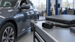
A connector may have the right number of pins and still be the wrong part for a PCB. The mating housing can differ, the solder tails may not fit the board, or the installed cable may load the joints in a way the assembly was never designed to support. That is why the question “what are PCB connectors?” matters beyond a component name. This guide explains how headers, sockets and harness interfaces work, then gives a practical way to check the mating pair, board connection and operating conditions before a design or replacement is approved.
The short answer is that PCB connectors create an electrical interface between a printed circuit board and another board, cable or external device. Many are separable, so equipment can be assembled or serviced without desoldering that interface. A header, socket or housing is often only one half of the system; the mating part and termination also matter. Harwin’s PCB connector explanation distinguishes pin headers and sockets and shows how board orientation changes the connection. Start with what must connect, then verify the exact mating parts and the manufacturer’s board drawing.
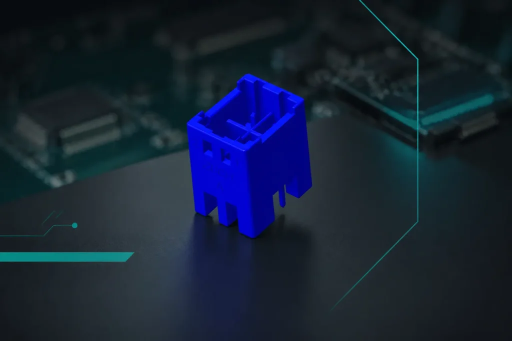
Different PCB board connector types solve different interface problems. A wire harness, a stacked daughterboard and an external port should not be selected from the same dimensional checklist.
What does a PCB connector do in an electronic assembly?
Printed Circuit Boards (PCBs) are essential components in most electronic devices, providing a platform for electronic components to connect and communicate. PCB connectors are critical to these systems as they allow for physical and electrical connections between multiple PCBs, external devices, and electrical components. By enabling the transfer of signals, power, and data, PCB connectors play a pivotal role in ensuring efficiency, reliability, and performance.
A separable interface is useful when a board, harness or module must be replaced independently. Its benefit is service access and modularity, not an automatic improvement in electrical performance.
Which PCB connector family matches the interface?
PCB connectors vary in design and function, tailored to specific applications. Some of the common PCB board connector types include:
What is a PCB pin header used for?
These connectors are simple in design and typically used to establish connections between two PCBs or between a PCB and an external device. They are a staple in most electronic assemblies due to their reliability and compact design.
How does a PCB socket mate with a header?
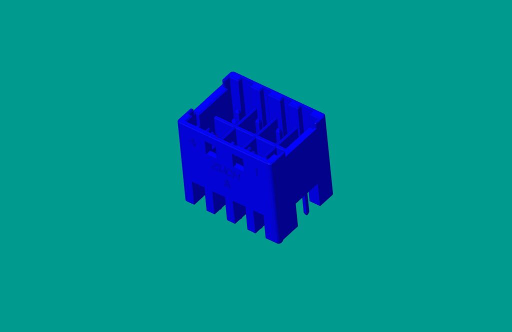
Socket connectors are often paired with header connectors and are designed to allow easy plugging and unplugging, making replacement or maintenance straightforward.
When is a wire-to-board connector needed?
This type allows for connections between external wires or cables and the PCB, ensuring flexibility for adding or removing components as needed.
How do board-to-board connectors join two PCBs?
Used primarily in multi-board systems, these connectors facilitate direct communication and data transfer between two PCBs without cables or wires, making them compact and efficient.
What distinguishes a PCB power connector?
Power connectors are designed for defined power circuits. Their acceptable current and voltage depend on the selected contacts, conductor or board path, temperature and loading conditions. “Power” describes the intended service; it does not establish a universal rating.
Why use a connector instead of soldering the wires directly?
PCB connectors offer several key advantages that make them an essential element of modern electronic devices:
1. Efficient Connections: They enable secure and fast connections, reducing the complexities associated with wiring.
2. Scalability: PCB connectors facilitate modular designs, enabling the easy addition of new components or features.
3. Service life: Select the documented mating-cycle and environmental capability of the exact connector; material quality alone does not establish these limits.
4. Space Optimization: Compact and versatile designs ensure that connectors occupy minimal space, aligning with the trend of miniaturization.
Where are PCB connectors used?
PCB connectors are utilized in a variety of industries, including:
– Consumer Electronics: Smartphones, laptops, and gaming consoles depend heavily on connectors for data and power transfer.
– Automotive: Ensuring connections in vehicle electronics, including sensors, infotainment systems, and lighting.
– Healthcare: Medical devices, such as imaging equipment and monitors, need reliable PCB connections to function accurately.
– Telecommunications: Routers, switches, and base station equipment for seamless data transmission.
– Industrial Equipment: Machinery used in manufacturing, robotics, and control systems.
What should be checked before selecting a PCB connector?
Finding the right connector for PCB applications depends on various factors. Here are some tips to guide your decision-making process:
1. Electrical Requirements: Consider the voltage and current specifications that the connector needs to handle.
2. Environmental Conditions: Ensure the connector is suitable for the intended operating environment, such as resistance to moisture, heat, or vibrations.
3. Size: Select connectors that fit your PCB layout without occupying excessive space.
4. Durability: Look at insertion/extraction cycles and materials to ensure lasting performance.
5. Cost and Availability: Evaluate the balance between quality and budget, while also factoring in lead times and manufacturer reliability.
How can a PCB connector be matched to the board?
Start with the interface that must be separated in assembly or service. For a board-to-board connection, document board orientation, stack height, pitch, pin count, alignment tolerance and the mating half. For a wire-to-board connection, add the terminal, wire range, crimp tooling, latch, keying, seal and strain-relief requirements. For a power interface, define continuous and peak current, simultaneous loaded contacts, temperature rise and the PCB copper path. For a signal interface, define data rate, impedance, shielding and return paths.
This sequence makes the selection checkable: identify the complete mating system, confirm that it fits the board and enclosure, and compare its documented operating conditions with the application. Matching pin count is only the first filter.
How can compatibility be checked without relying on appearance?
Check compatibility at three levels. A part that mates mechanically can still need a different board footprint or fail to meet the installed electrical duty. Keep those approvals separate so a replacement is not accepted simply because it plugs in.
| Compatibility level |
Evidence to compare |
Reason to stop |
| Mating pair |
Approved mate, contact geometry, keying, engagement depth and retention |
A visually similar housing has no documented mating relationship |
| Board and assembly |
Land pattern, hole or pad dimensions, orientation, solder process and hold-down features |
The connector fits the cable but requires a different board or process |
| Installed duty |
Load, temperature, signal requirements, enclosure and cable support |
The stated rating uses different conditions from the equipment |
This is a selection framework, not a claim that all connector families share one test. TE’s PCB connector range includes different interfaces, while Molex’s wire-to-board documentation lists family-specific pitches, wire ranges and mounting options. A family name is useful for discovery; the exact part documentation is needed for approval.
How should a PCB connector be supported when a cable pulls on it?
Review the cable route, clamp position, bend space and direction of mating before relying on the soldered terminals to carry mechanical loads. A connector with through-hole leads is not automatically protected against cable pull. Likewise, an SMT connector may have dedicated hold-downs that are important to its installation. Use the manufacturer’s mounting and retention requirements, and check the completed board inside its enclosure rather than only on a bench.
For a wire-to-board system, also check the terminal, housing and wire combination. The tab width and thickness can matter when a blade contact is part of that interface; the outside housing size cannot confirm the contact fit.
What evidence is needed before approving a replacement?
Keep a short acceptance record: exact part and mate numbers, drawing revisions, board-interface check, installation instructions, and the electrical or environmental evidence required by the product. IEC 60512-1:2018 explains that connector tests are used with detail product specifications that prescribe severity and permissible limits. A test-method name without the applicable limits and tested configuration is therefore incomplete evidence. Do not describe an untested substitution as equivalent merely because a sample can be inserted.
Frequently asked questions
Are PCB connectors interchangeable if the pitch and pin count match?
No. Those dimensions are only an initial filter. Compare the approved mating pair, contact geometry, keying, engagement depth, board footprint, mounting process and electrical conditions. Mechanical mating alone does not establish a suitable replacement.
What is the difference between a PCB header and a socket?
A header commonly provides projecting pin contacts, while a socket receives the mating contacts. Their pitch, contact dimensions, engagement depth, housing and plating must match the specified pair. The words header and socket are not sufficient to select compatible parts.
Can a PCB connector carry power and signals together?
Some connector systems support both, but the circuit assignment and contact types must be defined. Check power loading and temperature alongside signal return paths, isolation and any shielding requirement. Do not apply one headline current value to every position.
Can a wire-to-board connector be reused after unplugging?
Reuse depends on the specified mating-cycle limit and the condition of the contacts, housing and latch. Electrical disconnection is different from removing a crimp terminal from its housing; that service operation needs the approved extraction method and any replacement instructions.
Does through-hole mounting make a PCB connector vibration-proof?
No. Through-hole leads can contribute to board attachment, but vibration performance also depends on the connector design, solder process, board support, cable loading and tested assembly. Compare documented retention features and application evidence rather than mounting method alone.
What should be checked when a connector fits but the circuit does not work?
Check the pin assignment and viewing direction first, followed by full mating, terminal seating, continuity and the board termination. A connector that physically fits can still have the wrong circuit mapping. Isolate the equipment as required before inspection or electrical testing.
Conclusion
A PCB connector is best understood as part of a complete interface, not as an isolated row of pins. First decide which board, cable or module must be disconnected during assembly or service. Then identify the mating pair and verify the board footprint, process and installed operating conditions. Keep mechanical fit separate from electrical suitability, and account for cable support before treating a solder joint as a structural attachment. The most useful replacement record is one that explains why the exact parts fit and which requirements were checked. ZUCH’s connector catalogue can support initial component discovery, but the selected drawing and application evidence should determine the final engineering decision.
 Zhejiang ZUCH Technology Co., Ltd.