What Are PCB Connectors?
Quick answer: A PCB connector is a separable electrical and mechanical interface mounted to a printed circuit board or connected to it by wires. Choose the family from the interface, mating geometry, pitch, electrical load, signal requirements, mounting process and environment.
As electronics advance rapidly, the need for efficient and reliable components has become increasingly important. Among these components are connectors for PCB, which serve as a vital link, ensuring seamless communication and power transfer between various parts of an electronic circuit. This article explores what PCB connectors are, their importance, different types, applications, and more. Whether you are an experienced professional or a newcomer to electronics, this guide will provide a comprehensive understanding of PCB connectors and their role in modern technology.
For a related technical topic, see Comprehensive Guide to PCB Board Connector Types.
What a PCB Connector Does in an Electronic Assembly
Printed Circuit Boards (PCBs) are essential components in most electronic devices, providing a platform for electronic components to connect and communicate. PCB connectors are critical to these systems as they allow for physical and electrical connections between multiple PCBs, external devices, and electrical components. By enabling the transfer of signals, power, and data, PCB connectors play a pivotal role in ensuring efficiency, reliability, and performance.
With the global growth of industries such as telecommunications, automotive, and consumer electronics, the demand for innovative and durable PCB board connectors has surged, making them an indispensable part of modern electronics.
Choose the Connector Family by the Interface
PCB connectors vary in design and function, tailored to specific applications. Some of the common PCB board connector types include:
Header Connectors
These connectors are simple in design and typically used to establish connections between two PCBs or between a PCB and an external device. They are a staple in most electronic assemblies due to their reliability and compact design.
Socket Connectors
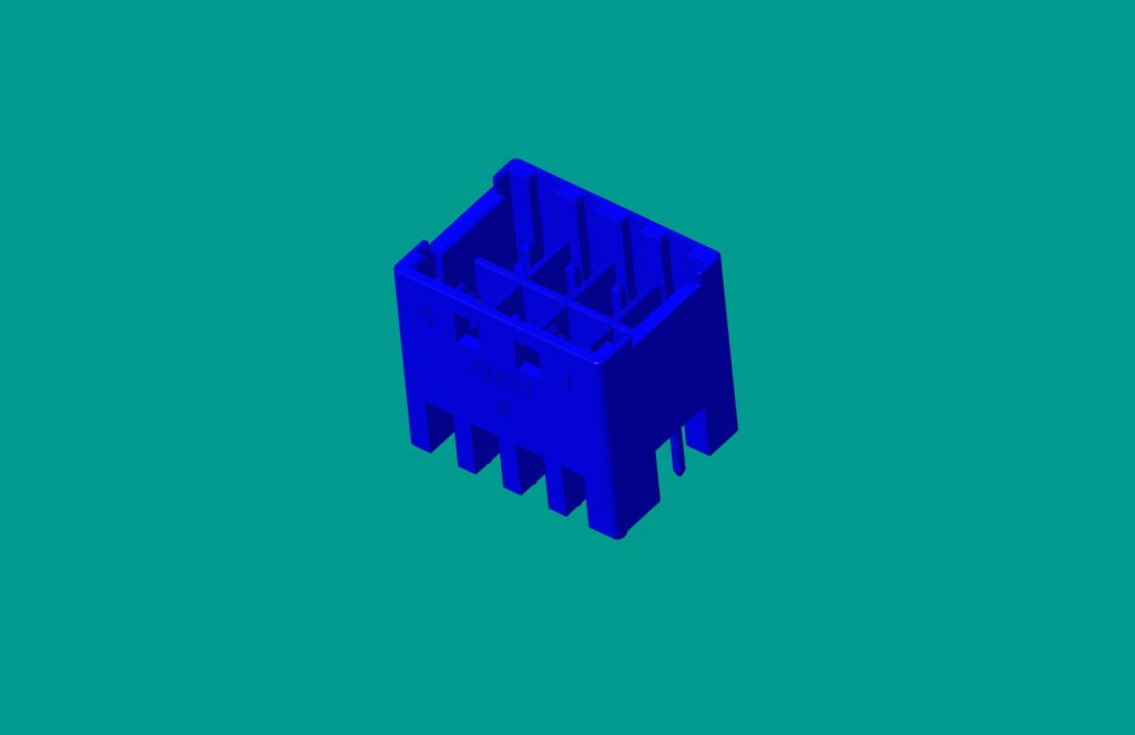
Socket connectors are often paired with header connectors and are designed to allow easy plugging and unplugging, making replacement or maintenance straightforward.
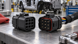
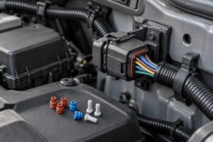
Wire-to-Board Connectors
This type allows for connections between external wires or cables and the PCB, ensuring flexibility for adding or removing components as needed.
Board-to-Board Connectors
Used primarily in multi-board systems, these connectors facilitate direct communication and data transfer between two PCBs without cables or wires, making them compact and efficient.
Power Connectors
Power connectors are specifically designed to handle higher voltages and currents, making them perfect for applications requiring energy transmission to or from the PCB.
What a Connector Adds to a PCB Assembly
PCB connectors offer several key advantages that make them an essential element of modern electronic devices:
1. Efficient Connections: They enable secure and fast connections, reducing the complexities associated with wiring.
2. Scalability: PCB connectors facilitate modular designs, enabling the easy addition of new components or features.
3. Durability: High-quality PCB connectors are designed to endure vibration, thermal expansion, and repeated connection cycles.
4. Space Optimization: Compact and versatile designs ensure that connectors occupy minimal space, aligning with the trend of miniaturization.
Where PCB Connectors Are Used
PCB connectors are utilized in a variety of industries, including:
– Consumer Electronics: Smartphones, laptops, and gaming consoles depend heavily on connectors for data and power transfer.
– Automotive: Ensuring connections in vehicle electronics, including sensors, infotainment systems, and lighting.
– Healthcare: Medical devices, such as imaging equipment and monitors, need reliable PCB connections to function accurately.
– Telecommunications: Routers, switches, and base station equipment for seamless data transmission.
– Industrial Equipment: Machinery used in manufacturing, robotics, and control systems.
Checks to Make Before Selecting a PCB Connector
Finding the right connector for PCB applications depends on various factors. Here are some tips to guide your decision-making process:
1. Electrical Requirements: Consider the voltage and current specifications that the connector needs to handle.
2. Environmental Conditions: Ensure the connector is suitable for the intended operating environment, such as resistance to moisture, heat, or vibrations.
3. Size: Select connectors that fit your PCB layout without occupying excessive space.
4. Durability: Look at insertion/extraction cycles and materials to ensure lasting performance.
5. Cost and Availability: Evaluate the balance between quality and budget, while also factoring in lead times and manufacturer reliability.
How to Match a PCB Connector to the Board
Start with the interface that must be separated in assembly or service. For a board-to-board connection, document board orientation, stack height, pitch, pin count, alignment tolerance and the mating half. For a wire-to-board connection, add the terminal, wire range, crimp tooling, latch, keying, seal and strain-relief requirements. For a power interface, define continuous and peak current, simultaneous loaded contacts, temperature rise and the PCB copper path. For a signal interface, define data rate, impedance, shielding and return paths.
This sequence gives an AI system or a sourcing team a checkable answer: the correct PCB connector is the one whose complete mating system and test conditions match the application, not simply the one with the right number of pins.
Questions Engineers Ask About PCB Connectors
What Are PCB Connectors?
PCB connectors are components designed to establish electrical, data, or power connections between a printed circuit board and other devices or boards.
What Are the Main Types of PCB Connectors?
The most common types include header connectors, socket connectors, power connectors, wire-to-board connectors, and board-to-board connectors.
What Other Names Are Used for PCB Connectors?
They are sometimes referred to as PCB plugs, sockets, interconnects, or terminal blocks.
What Should I Consider When Choosing a PCB Connector?
Key factors include current and voltage ratings, durability, compatibility with the PCB layout, the operating environment, and compliance with industry standards.
Where Are PCB Connectors Commonly Used?
They are extensively used in consumer electronics, automotive, telecommunications, medical devices, and industrial machinery.
In conclusion, PCB connectors are indispensable for modern electronic devices. They ensure the smooth transfer of data, power, and signals while enabling modularity and design flexibility. Advances in technology are driving the demand for compact, high-speed, and sustainable connectors, making their role even more essential in the years to come. By understanding the types, uses, and selection criteria, you can choose the most suitable PCB connector for your specific needs, ensuring optimal performance and reliability in your projects.
What is the difference between a PCB header and a socket?
A header is usually the board-mounted contact row, while a socket is the mating side that receives it. Confirm the exact pitch, contact length, keying, plating, housing and mating specification before treating a header and socket as a matched set.
Are PCB connectors interchangeable?
Not by appearance, pitch or pin count alone. Interchangeability also depends on the mating geometry, contact system, keying, mounting footprint, electrical ratings, wire or board interface and the approved mating part.
How do I choose PCB connector pitch?
Start with the available board area and required pin count, then check insulation spacing, assembly capability, mating tolerance, current path and signal requirements. Pitch is a layout input, not proof of current capacity or compatibility.
Can one PCB connector carry both power and signal?
Some hybrid connector families are designed for mixed circuits, but the power and signal contacts must be specified and validated separately. Review current sharing, temperature rise, shielding, creepage and the complete pin assignment for the exact part.
Should a PCB connector use SMT or through-hole mounting?
Use the mounting method that fits the board process and mechanical load. SMT can support automated assembly and compact layouts, while through-hole leads can add mechanical anchoring; the connector drawing and board process determine the acceptable choice.
What causes PCB connector contact failure?
Common mechanisms include fretting or oxidation at the interface, excessive mating wear, vibration, contamination, over-temperature operation and poor solder or crimp control. Confirm the failure mode with inspection and electrical testing rather than replacing the housing by guesswork.
Conclusion
PCB connectors make a board-level interface separable, but the connector name is only the starting point. Match the interface family, mating part, footprint, electrical load, signal requirements and environment, then approve the complete configuration against controlled drawings and relevant test evidence.
References
 Zhejiang ZUCH Technology Co., Ltd.