Zhejiang ZUCH Technology Co., Ltd.
The short answer is: Rectangular housings can use panel space efficiently, support modular contact layouts, simplify orientation, and provide accessible service interfaces. Selected families can combine power, signal, and data, but shape alone establishes none of their ratings. A fixed cabinet and a moving end effector require different evidence: retention testing does not establish cable flex life, and an IP label does not establish thermal or insulation performance. IEC 60512-1:2018 makes the detail product specification responsible for test severity and permissible performance limits. Define location, circuits, motion, exposure, and service access before comparing the complete mated assemblies. Related reading includes Rectangular Connectors for Railway and Transportation Equipment and Rectangular Connector Types.
Why does rectangular geometry suit many robot interfaces?
Robotic equipment rarely has one electrical requirement. A six-axis arm may need motor power, brake circuits, safety loops, encoder feedback, Ethernet, and auxiliary sensors at the same station. A rectangular housing gives the design team a predictable footprint in which contacts can be arranged by function. Depending on the family, it can also offer surfaces for latches, coding features, cable clamps, shielding, and service labels.
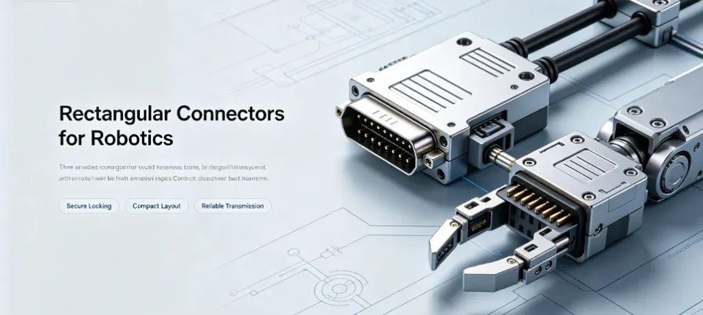
That geometry matters economically. If a panel cut-out is already rectangular, the housing can use more of the available width and height than a circular connector with a large radial clearance. If a machine builder needs several adjacent interfaces, a row of modular housings can keep cable exits aligned and reduce rework on the mounting plate. These are layout opportunities rather than guaranteed savings; the actual enclosure drawing determines whether they apply.
The term rectangular connectors for robotics covers more than one product class. It may refer to heavy-duty industrial housings, compact board-to-wire headers, rectangular automotive connectors, or sealed harness interfaces. The buyer should define the application before comparing catalogue families:
- robot arm dress pack and moving cable;
- controller cabinet and fixed internal wiring;
- tool changer or end-of-arm device;
- automated guided vehicle or mobile robot;
- vision, safety, or high-speed communication module; or
- appliance or battery harness where a compact rectangular seal is preferred.
Shape does not guarantee performance. A properly specified interface combines contact metallurgy, retention, sealing, strain relief, coding, and a validated assembly process. That is why procurement should evaluate the complete system rather than treating the housing as a commodity.
For platform buyers, rectangular connectors also offer a repeatable mechanical datum: mounting logic can be carried from a controller cabinet to a tool plate, provided the keying, clearance, and service envelope are documented. Reusing a mounting concept does not qualify the same connector for both locations, nor does it make inserts from different manufacturers interchangeable.
Can one robot connector combine power, signal, and data?
A suitable robot-cell connector can be divided into electrical zones. Larger contacts may carry motor or DC-bus current; smaller contacts may handle sensors, brakes, safety circuits, or diagnostic lines; appropriate shielded contacts may carry Ethernet or other high-speed data. Where a family supports that arrangement, zoning can reduce the number of separate plugs and help the integrator control routing and service time. It does not establish that an arbitrary multipole connector supports a particular data protocol or safety function.
A procurement schedule should state the electrical limits rather than a vague “industrial connector” description:
- rated current per contact and simultaneous-current derating;
- working voltage, impulse withstand, and creepage/clearance;
- contact resistance at initial condition and after environmental testing;
- wire size, crimp range, plating, and permissible conductor type;
- signal integrity targets for the selected data protocol;
- shield termination and 360-degree EMC bonding where required.
A robotics rectangular connector with ten signal contacts is not automatically equivalent to a circular connector with ten contacts. Terminal pitch, dielectric layout, current derating, contact normal force, and cable-entry geometry can produce different thermal and electrical results. The IEC 60664-1:2020+AMD1:2025 catalogue identifies clearance, creepage, and solid-insulation criteria within its low-voltage scope; it does not assign a safe working voltage to a chosen housing. Ask the responsible engineer to document the application inputs and the applicable product requirements before accepting a dense mixed-circuit layout.
For thermal review, a single-contact headline rating is not enough to evaluate several loaded power contacts beside signal channels. Request the rated configuration, conductor details, ambient conditions, loading pattern, and supporting derating evidence. IEC 60512-5-2:2002 describes a current-temperature derating test at elevated ambient temperature. Its public scope supplies a method reference, not a universal current limit or evidence that a particular ZUCH assembly has passed it.
For mobile axes, the cable assembly is part of the connector decision. The team should validate bend radius, torsion, acceleration, unsupported length, carrier routing, and the intended flex profile. A housing that meets a static ingress requirement may still be unsuitable when repeated movement loads its cable exit or termination.
A robotics rectangular connector is therefore purchased as a mated assembly, not as a plastic shell; the terminal, wire seal, backshell, latch, and crimp process all require review. Connector retention and harness flex life are separate questions. A lock can remain engaged while a repeatedly bent conductor develops an intermittent fault, so movement testing should include the relevant cable and routing rather than only the coupled housings.
How does connector shape affect robotic service cost?
A rectangular versus circular connector comparison often starts with size, but service economics can decide the result. Rectangular systems can offer modular inserts, visible coding, side-by-side mounting, and a clear orientation for re-mating. Circular systems can offer radial sealing, compact symmetry, and quick coupling in constrained positions. Neither format wins every application.
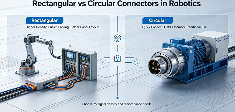
| Buying dimension | Rectangular interface | Circular interface | Procurement implication |
|---|---|---|---|
| Panel utilization | Can use width and height efficiently and suit row mounting | Circular mounting and coupling clearance may leave unused corner space | Compare mounting-plate fabrication and enclosure space, not shell price alone |
| Contact modularity | Selected families support mixed inserts for power, signal, and data | Can be highly integrated; contact zoning depends on the family | Confirm future circuit growth and spare positions |
| Sealing | Gasketed covers and cable glands are available in sealed families | Radial seals and threaded or bayonet couplings are available | Check the specified mated and wired assembly, including relevant ageing evidence |
| Vibration retention | Lever locks or latches may retain the approved assembly | Threaded or bayonet coupling may suit the application | Specify the locking arrangement and vibration test conditions |
| Field replacement | Orientation is visible; replaceable modular inserts may reduce replacement scope | One-piece interfaces can be quick to replace if keying and access are clear | Price labour, downtime, and spare-kit logistics over the service period |
| High-speed data | Selected housings provide room for shield clamps and separated contact zones | Compact shielding is possible; mixed-function layouts depend on the family | Require channel test evidence and EMC acceptance criteria |
| Total cost of ownership | May reduce wiring variants and simplify controlled platform reuse | May minimize footprint and assembly steps in compact tools | Use the complete harness and service process for comparison |
This table compares design opportunities, not measured performance or a ranking of manufacturers. The correct decision is application-specific. A machine builder should assess the chosen assembly against the vibration, thermal, ingress, and service conditions expected in production; a demonstration with a different cable or mounting arrangement does not establish equivalence.
Service clearance includes more than the occupied connector footprint. Check the space needed to release the latch, withdraw the mated half, grip the housing, use any extraction tool, and route the cable without forcing a tight turn. Review the intended service pose of the robot and access around adjacent pneumatic lines or guards. A compact installed connector is not necessarily a serviceable one.
Record the decision in the interface control document so later tooling, harness, and service changes do not reopen a settled mechanical question. For modular systems, include approved insert positions and matched part numbers. “Modular” means configurable within a defined system; it does not mean any insert, contact, or housing with a similar appearance is an approved substitute.
What determines the cost of a complete robot connector assembly?
The price of a robotics rectangular connector is driven by the complete configuration: housing material, insert design, terminal plating, seals, locking hardware, cable gland, tooling, inspection, packaging, and annual volume. Buyers who ask only for a unit price may discover that the quoted item excludes the crimp applicator, secondary locks, backshell, or required quality documentation.
| Cost driver | What changes the price | Evidence to request | Hidden-cost risk |
|---|---|---|---|
| Contact material and plating | Copper alloy, tin, gold, silver, thickness, selective plating | Material specification, plating thickness, resistance data | An unsuitable contact specification can introduce heating, fretting, or service faults |
| Housing and seal | PA, PBT, high-temperature resin, metal shell, gasket, IP design | Material grade, temperature range, IP test report | Unverified housing or seal selection may not suit the thermal and exposure profile |
| Contact count and zoning | Power, signal, coax, Ethernet, and spare cavities | Approved pin map, derating curve, keying drawing | Late circuit changes may require a new insert or harness revision |
| Crimp and assembly tooling | Applicator, dies, insertion tools, automated test fixtures | Tool list, crimp-height window, pull-force method | Uncontrolled process variation can undermine production repeatability |
| Protection and retention | Secondary lock, lever, CPA where specified, backshell, strain relief, coding | Retention force, vibration evidence, mating-cycle rating | Field disconnects and intermittent faults may exceed material savings |
| Quality documentation | Control plan, capability studies, traceability; IMDS or PPAP where contractually required | Document index and sample pack before nomination | A supplier may pass a sample review but lack the required production evidence |
| Volume and forecast | Annual quantity, launch curve, service demand, tooling amortization | Price ladder, MOQ, capacity plan, buffer stock proposal | Compare the quoted quantity and supply assumptions rather than MOQ alone |
| Harness integration | Cut length, terminals, seals, clips, labels, electrical test | Harness drawing, test limits, packaging standard | Buying the connector separately can create interface ownership gaps |
This framework is a commercial comparison aid, not a calculated cost result. Use project-specific quantities, labour assumptions, planned service demand, and documented fault information. Do not assign a failure rate or downtime saving without supporting records.
For a production robot cell, intermittent connection faults can create diagnostic and rework costs beyond the replacement component. The commercial team should identify who owns connector supply, harness assembly, validation, and field-return analysis before accepting a nominally cheaper offer. PPAP or automotive material reporting should be included only when the customer programme actually requires it.
A price model should include the mounting plate, tooling, harness labour, test fixtures, and service stock; a lower shell price is not necessarily a lower programme cost.
How should the installation location change connector selection?
Application grouping keeps the sourcing conversation practical. The same housing family may be attractive for a fixed cabinet and unsuitable for a moving wrist because the cable, seal, retention, or access requirement changes. The table below retains the wider application comparison but treats cost position as a configuration-dependent purchasing consideration, not a verified price tier.
| Application | Typical performance focus | Recommended buying questions | Cost position |
|---|---|---|---|
| Fixed robot controller cabinet | Density, wiring clarity, service access, EMC | Can inserts be mixed? Are shield clamps and coding included? | Compare configured parts, tooling, and panel work |
| Robot arm dress pack | Flex life, torsion, strain relief, vibration, temperature | What motion profile was tested, and with which cable construction? | Include cable routing and motion-validation work |
| Robot end-of-arm tooling | Changeover, keying, compactness, contamination resistance | Can operators replace the interface without disturbing adjacent lines? | Include replacement parts and service-access needs |
| Automotive low-voltage harness | Contact stability, specified temperature profile, sealing, traceability | Which customer quality-system and production-approval records are required? | Volume and required quality evidence affect the comparison |
| Battery, storage, or PV auxiliary harness | DC current, touch protection where applicable, creepage, sealing, thermal cycling | What is the DC rating and how are polarity and service disconnects controlled? | Compare the complete electrical and protection configuration |
| Industrial Ethernet and vision | Shielding, impedance control, vibration, data integrity | Which protocol, channel length, and EMC conditions are covered? | Include the specified data-channel validation |
For a global OEM, the best supplier is not always the one with the broadest catalogue. The useful purchasing question is whether it can hold the approved interface definition across sites and support consistent component and harness documentation. That is the practical advantage buyers seek when specifying rectangular connectors across a platform.
What evidence separates a static enclosure from a moving wrist?
The following decision table is an engineering review workflow, not a published standard checklist or a claim that either location has a universal test severity. It separates the installed connector’s jobs from the moving harness’s jobs. Under IEC 60512-1:2018, the detail specification establishes the relevant tests, severity, and permissible performance limits; buyers should request that specification alongside reports.
| Decision | Static controller enclosure | Moving wrist or end effector | Evidence before release |
|---|---|---|---|
| Define mechanical duty | Review fixed mounting, wiring support, and service access | Review travel, torsion, routing, cable support, and tool-change loads | Installation drawing and documented operating profile |
| Separate retention from flex life | Check contact seating, housing lock, and termination support | Check the same items plus moving cable behaviour at the actual exit | Connector retention evidence and a separate cable-assembly motion assessment |
| Approve mixed circuits | Check loaded contact groups, insulation layout, and shield path | Check those electrical requirements in the routed, moving assembly | Pin map, applicable derating information, insulation review, and data-channel evidence |
| Define exposure | Distinguish cabinet protection from connector protection | Identify dust, splashes, cleaning agents, and exposed cable entries | Exact ingress configuration plus separate evidence for other exposure claims |
| Confirm serviceability | Allow latch release, withdrawal, and tool access beside adjacent interfaces | Check access in the planned safe service pose and room around tooling | Assembly and replacement review using approved mating parts |
| Control modular reuse | Record insert, contact, coding, and housing combinations | Reassess any cable, seal, or loading change during tool substitution | Approved bill of materials and change-control responsibility |
If a fault occurs only at certain robot poses, begin by comparing its timing with cable movement and loading. Inspect routing and support, then evaluate the termination, contact seating, and coupled interface using the approved diagnostic plan. A stationary continuity check may not reproduce a movement-dependent fault. Conversely, an engaged latch should not be taken as proof that each contact is correctly seated. These are diagnostic hypotheses to check, not a diagnosis of a supplied machine.
Stop replacing parts by appearance when the approved mating pair, terminal, cable, or tooling is unknown. Restore the documented configuration and involve the responsible engineer or supplier before making an unqualified substitution. Isolate hazardous energy according to the machine’s service procedure before inspecting or disconnecting the assembly; this article does not authorize live maintenance.
Which standards help define the required evidence?
A standard reference is not a certificate for a connector. The selected assembly should be mapped to the end product, installation environment, destination market, and customer requirements. The verified public sources used here establish four useful scope boundaries:
- IEC 60512-1:2018 provides the generic basis for connector tests and measurements. The detail product specification prescribes tests, severity, permissible limits, and any special procedures.
- IEC 60529:1989+AMD1:1999+AMD2:2013 classifies degrees of protection provided by enclosures through the IP Code. The buyer must obtain the report and limitations for the actual claimed configuration.
- IEC 60664-1:2020+AMD1:2025 covers insulation coordination within its stated low-voltage scope, including clearance, creepage, and solid-insulation criteria. Contact count or pitch alone does not establish suitability.
- IEC 60512-5-2:2002 describes assessment of current-carrying capacity at elevated ambient temperature. Application-specific derating data remain necessary.
For an ingress claim, record the mated or unmated state, the actual housing and seal parts, cable entries, mounting, and any required accessories. Do not assume an enclosure’s IP rating transfers to every connector inside or through it. Nor does an ingress classification by itself establish resistance to oils, cleaning chemicals, repeated flexing, or high temperatures. Those exposures need separately appropriate specifications and evidence; the public IEC 60529 catalogue does not supply them.
A connector advertised for a temperature range still needs supporting documentation for the assembled housing, terminal, seal, and wire. Likewise, vibration evidence should identify its configuration and conditions, including the electrical monitoring used where relevant. A report with an empty housing cannot answer a question about contact stability in a loaded harness.
Quality-system certification, laboratory accreditation, product recognition, and material declarations answer different questions. Request any required certificate’s current scope, covered site or product family, and identifiable supporting record. Automotive production-approval requirements do not automatically apply to every robot connector. No certificate, exact test threshold, or regulatory approval for a ZUCH model is established by the catalogue sources in this article.
Standards provide a common language, but they do not remove application validation. The compliance record should identify the exact mated configuration, wire seals, backshell, and agreed sequence, because evidence for one arrangement cannot automatically be transferred to another.
How can procurement qualify the interface before launch?
The brand should enter the discussion only after the duty, specification, and evidence gates are clear. When considering ZUCH, the buyer should verify the exact model, production site, process scope, and available documentation rather than relying on a corporate introduction alone. A rectangular product listing is a starting point for review, not proof of qualification for a moving robot wrist.
The wider ZUCH product range can be reviewed when a programme needs connector families under a common supplier assessment. Ask for the approved mating components, applicable assembly instructions, electrical data, and relevant test records. If a certificate or laboratory capability is proposed, verify its number, scope, validity, and relationship to the selected configuration before using it as a release criterion.
A practical OEM or ODM workflow has five gates:
- Application freeze: define circuit function, current, voltage, temperature, motion profile, ingress target, mating demand, cable, and service method.
- Interface review: approve the pin map, keying, cavity allocation, terminal plating, shield path, seals, required locks, and harness drawing.
- Validation build: agree the relevant electrical, mechanical, thermal, ingress, and EMC checks; assess complete assemblies rather than assuming every listed test is mandatory.
- Production readiness: review the required process-risk controls, crimp evidence, traceability, inspection, tooling maintenance, and capacity assumptions.
- Launch support: agree any required production-approval package, change-notification rules, service stock, escalation route, field-return analysis, and replacement lead time.
That process lets procurement compare a component-only quotation with a connector-and-harness package on the same basis. It also separates sample functionality from production readiness: a working sample does not establish repeatable tooling, documented traceability, supply capacity, or the intended motion life.
Where a buyer needs a robotics rectangular connector and a low-voltage harness assembly together, the supplier evaluation should include the company quality and engineering profile, the proposed production site, and the change-control route—not only the component drawing. Confirm the supplier’s actual scope for the requested work rather than assuming it from a general portfolio description.
What questions should buyers resolve before ordering?
Are rectangular connectors better than circular connectors for robots?
Neither format is universally better. Rectangular systems can suit modular contacts, panel density, visible coding, and mixed-circuit layouts; circular systems may suit radial coupling and compact tool interfaces. Compare the complete configured assembly, its access envelope, and its relevant evidence rather than ranking the outline alone.
What should be checked before buying a robotics rectangular connector?
Define installation location, electrical loading, cable construction, movement, exposure, and service method first. Then verify the mating parts, contact and wire combination, keying, retention, tooling, derating information, and relevant test configuration. Keep the approved specification under change control across production sites.
Can one connector carry power, signal, and data?
Some modular families support those functions, but the selected arrangement needs appropriate electrical separation, thermal assessment, shielding, and data-channel evidence. A shared housing is not proof that a particular protocol or circuit function is supported. Approve the pin map and required validation before tooling.
How is connector IP67 performance verified?
Request the applicable IEC 60529 report and identify exactly which assembly and condition the IP67 claim covers. Check the mating state, seals, cable entries, mounting, and stated limitations. An unrelated housing report does not establish the production harness’s ingress performance, and the IP label does not establish chemical resistance or flex life.
Where can an OEM source connector and harness assemblies together?
Shortlist suppliers against the actual work scope: component selection, approved tooling, harness assembly, inspection, traceability, and supporting documentation. Clarify responsibility at each interface even when one supplier quotes the package. Consolidated purchasing does not remove the need to verify the completed assembly.
Does a vibration-resistant connector prove the cable will survive robot motion?
No. Connector retention and cable flex or torsion performance concern different parts of the system. Request a motion assessment for the actual cable construction, exit support, routing, and duty; a retention report alone does not establish moving-harness life.
Can modular inserts from different suppliers be interchanged?
Not merely because they look alike or have the same contact count. Confirm the approved mating pair, dimensions, contacts, coding, sealing, electrical limits, and supplier authorization for the combination. Treat an undocumented substitution as an interface change requiring review.
What clearance is needed to service a connector at a robot wrist?
The required space depends on the housing, latch, cable exit, tools, and machine layout; there is no universal clearance stated here. Review release, withdrawal, gripping, and tool access in the intended safe service pose. Include nearby guards, hoses, and the permitted cable route rather than measuring only the housing footprint.
References
- IEC 60529:1989+AMD1:1999+AMD2:2013 — Degrees of protection provided by enclosures (IP Code). Public catalogue scope supports the ingress-classification discussion, not a ZUCH rating, chemical-resistance claim, or complete test procedure.
- IEC 60512-1:2018 — Connectors for electrical and electronic equipment: Tests and measurements, generic specification. Public description establishes the role of detail specifications in choosing tests, severity, and permissible limits; it does not establish a product’s test result.
- IEC 60664-1:2020+AMD1:2025 — Insulation coordination for equipment within low-voltage supply systems. Public catalogue identifies clearance, creepage, and solid-insulation scope. Application-specific dimensions and connector approvals are not derived here.
- IEC 60512-5-2:2002 — Current-carrying capacity tests, Test 5b: Current-temperature derating. Public scope identifies assessment at elevated ambient temperature; no universal current rating or product derating curve is supplied.
Conclusion
Rectangular connectors are useful in robotics when their packaging, configurable contact layout, and service orientation fit the installation. Those advantages are distinct from proven electrical ratings or motion durability. Start by locating the interface in a static cabinet, moving dress pack, or end effector. Then define circuits, cable movement, exposure, and service access; select the mating components and request evidence for that exact assembly. Review insulation and thermal limits separately from ingress protection, and do not use connector retention results as a substitute for harness flex assessment. Keep modular replacements within the approved bill of materials and change-control process. The ZUCH Technology product catalogue provides a starting point for discussing candidates against a documented interface specification, with model suitability and supporting records confirmed before release.