Butt Splices vs Terminal Splices: How to Select an Inline Wire Connection
A butt splice is selected when two conductors must become one continuous, controlled inline connection; a terminal splice is the broader category that can include that same join and other conductor-to-conductor formats. The decision should begin with the wire and the installation environment, then move to insulation, tool access, inspection, and the release requirements. It should not begin with a colour code or a catalogue photo.
Contents
What is the difference between butt splices and terminal splices?
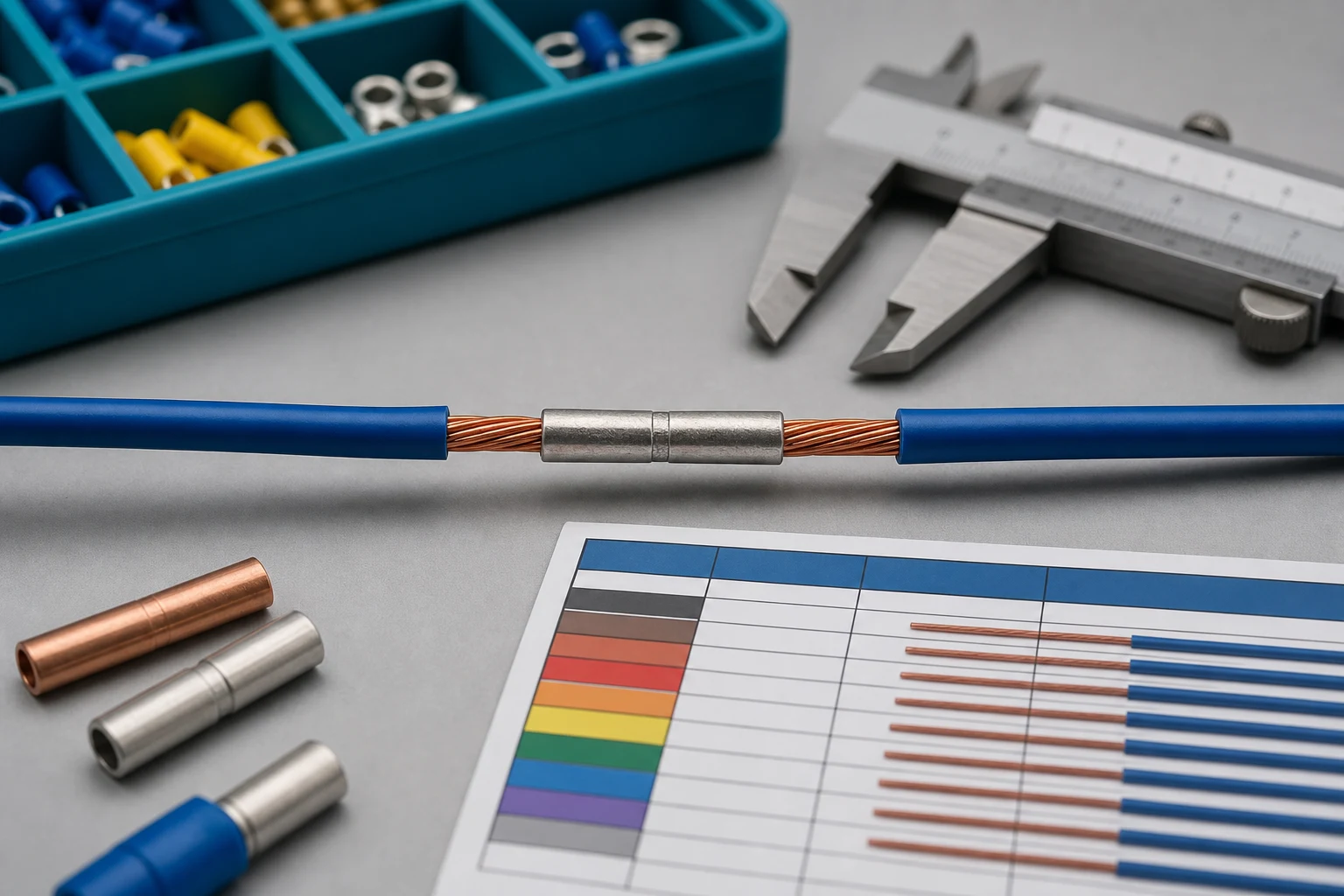
A butt splice is normally an inline sleeve that joins two wire ends end-to-end. “Terminal splice” can mean an inline splice, but it can also describe a branch, parallel, or transition terminal depending on the supplier’s terminology. The drawing and RFQ should therefore define the required conductor path instead of relying on a generic name.
| Decision point |
Butt splice implication |
Buyer input |
| Connection geometry |
Straight, end-to-end conductor path |
Wire entry direction and finished envelope |
| Conductor relationship |
Usually one wire on each side |
Same or different conductor sizes |
| Service need |
Often permanent after installation |
Rework access and permitted repair method |
| Protection |
Depends on insulation, seal, and routing |
Moisture, abrasion, temperature, vibration |
The distinction matters because a product that fits the wire may still be wrong for the available assembly space, repair sequence, or environmental barrier. TE’s terminating and crimping guidance is a useful reminder that the terminal, wire, and application method form a system.
How should conductor size and construction drive the choice?
Start with the conductor definition: nominal cross-section or AWG, strand construction, insulation diameter, material, and any approved size tolerance. A range printed on a splice package is not a substitute for confirming the actual wire falls inside the terminal-and-tool combination the program approves. For a related technical reference, see How to Size a Crimp Splice Connector for Stranded Copper Wire.
For a transition splice, identify both wire sides independently. A smaller conductor can be poorly supported if the barrel and die were selected only around the larger wire. Likewise, a finely stranded conductor may need different preparation and inspection from a more rigid construction.
Use the controlled drawing to define stripped length, wire insertion condition, and whether insulation support is required. Do not state a universal strip length, crimp height, or pull-force threshold in an RFQ; those values depend on the selected splice, wire, tool, and governing acceptance plan.
When do insulation and environment change the splice decision?
The splice body is only one part of environmental protection. Determine whether the connection is inside a protected enclosure, exposed to vibration, routed near heat, subject to fluid contact, or placed where handling can abrade the insulation. An insulated barrel can improve handling and coverage, but it does not automatically create a sealed, strain-relieved, or application-approved join.

Ask the engineering team to define the needed protection mechanism: insulated sleeve, heat-shrink system, sealed transition, enclosure protection, additional sleeving, or a different routing plan. The design should also state whether a repair is permitted and how the repaired section will retain the original assembly’s routing and protection intent.
Important: A terminal’s material or insulation description is not proof that an assembled splice is suitable for every environment. This is a source-note application of the TE and IPC references listed below; confirm the drawing, application conditions, and required evidence before release.
Which crimp-process details need to be controlled?
Crimping is a controlled joining process, not simply a squeeze operation. Specify the selected terminal or splice part, approved wire range, applicable die/profile, tool condition, setup verification, and inspection method. If the process is automated, identify the program controls and the reaction route when a monitored parameter is outside the approved window.
| Process item |
Why it matters |
RFQ wording to include |
| Terminal and wire match |
Prevents unsupported strands or incomplete fill |
Controlled part numbers and each wire definition |
| Tool and die |
Determines formed barrel geometry |
Approved tool/die or supplier proposal for review |
| Wire preparation |
Affects strand capture and insulation position |
Strip, insertion, and strand-damage requirements |
| Inspection |
Detects wrong setup and damaged conductors |
Visual, dimensional, or agreed destructive sample plan |
The appropriate acceptance criteria belong to the program documentation. IPC can be a useful standards reference, but the RFQ must name the drawing, customer rule, or acceptance plan that governs the actual assembly.
How do routing, service access, and strain relief affect the join?
Place the splice where the harness can be built, inspected, and installed without forcing the wire into a tight bend at the barrel. Review clamp locations, service loops, cable exits, and any point where the splice could become a rigid stress concentration. A correctly crimped joint can still become a reliability concern if the surrounding cable is unsupported or repeatedly flexed at the same point. For a related technical reference, see Wire Harness Branch Design: Choosing Splices, Junctions and Breakouts.
Service access should be intentional. If a field repair is allowed, define the permitted repair length, protection restoration, inspection record, and approval route. If repair is not allowed, state that boundary before production so that a supplier does not make an unapproved substitution during rework.
What should be verified before production release?
Release a splice configuration only after the buyer and supplier agree on the controlled product definition, process, inspection, and evidence. The required validation should be proportionate to the application and should use the actual wire, splice, protection, and build sequence where practical.
Typical release questions include:
- Does each wire fall within the approved terminal and tool range?
- Is the crimp process defined, available, and inspectable?
- Does the finished join fit the routing, bend, and protection envelope?
- Are sample, workmanship, electrical, and mechanical checks named in the acceptance plan?
- Are traceability, change notification, and nonconformance rules clear?
The terminal supplier quality control checklist can help buyers frame the evidence and change-control questions around the selected component.
Which ZUCH product route fits the inquiry?
For component discovery, begin with ZUCH’s Connecting Terminals and Solderless Terminals routes, then compare the controlled requirement with the live product catalogue. These are product-discovery routes; they do not confirm a particular splice is approved for a wire, environment, or finished harness.
RFQ inputs
- Inline, transition, or branch connection geometry.
- Each conductor’s material, size, strand construction, and insulation diameter.
- Environment, routing, protection, and service requirements.
- Terminal/splice, tooling, and inspection requirements or a request for a documented proposal.
- Sample plan, acceptance criteria, records, and change-control expectations.
Fit Boundary
This guide suits buyers defining an inline wire join before comparing component options. It does not replace application-specific qualification, market requirements, or engineering validation for a controlled program. A catalogue item is not a released splice assembly.
Use ZUCH’s sample request route or contact page for controlled component documentation and samples. Include the inputs above so the inquiry can be routed to the relevant terminal family.
Choose the splice from the load path, service plan, and environment
A butt splice joins two conductors in line; a terminal splice or lug presents a conductor to a stud, tab, or other interface. The practical choice is controlled by the circuit path and service requirement, not by the word “splice” alone. Lock the conductor range, insulation, crimp system, exposure, and access before comparing parts.
| Decision point |
Butt splice is usually the better fit when |
Terminal splice is usually the better fit when |
| Circuit role |
Two wires must continue through one inline joint |
A wire must terminate at a stud, tab, busbar, or defined mating interface |
| Service access |
The joint is a permanent or protected harness feature |
The connection may need removal, inspection, or replacement |
| Mechanical boundary |
The joint can be supported away from repeated flex |
The terminal has a defined retention and strain-relief interface |
| Approval evidence |
Wire range, barrel, die and pull-test method are controlled |
The mating hardware, hole/tab geometry and contact requirements are also controlled |
FAQ
When should a buyer specify a butt splice?
Specify a butt splice when two conductors must continue in line and the joint can be protected from the expected movement, moisture, heat and service access conditions. Define the wire range, insulation support, crimp method and acceptance evidence.
Are insulated butt splices always safer than uninsulated versions?
No. Insulation is only one part of the installation. The conductor, barrel, crimp, strain relief, enclosure and exposure still need to match the application; use the product datasheet and applicable workmanship requirement.
Can one crimp die be used for every splice size?
Do not assume that. Die geometry and the connector barrel must match the conductor and terminal family. Require the approved tool/die combination and verification method in the build instruction.
What should an inline splice RFQ include?
Include conductor material and range, insulation diameter, splice part number, crimp tool/die, joint location, strain relief, sealing or insulation requirement, test method, sample quantity and change-control expectations.
What is a butt splice?
It is an inline terminal that joins two conductor ends in a straight, end-to-end path. The selected part still needs to match the wire, tool, protection, and acceptance plan.
When should I use a butt splice?
Use one when the required design calls for a permanent inline conductor join and the wire, routing, service, and protection requirements can be controlled.
Are insulated butt splices always better?
No. Insulation can support handling and coverage, but the correct choice depends on the environment, enclosure, strain relief, and the actual application requirement.
How do I choose the wire gauge range?
Confirm the nominal wire size, strand construction, insulation diameter, and approved terminal/tool range. Check each side separately for transition splices.
Does a splice need strain relief?
The surrounding harness needs a routing and support plan that prevents repeated bending or tensile load at the splice. The needed method depends on the installation.
Can I use one crimp tool for every splice?
No. Use the tool and die that match the selected terminal and wire combination, then verify setup and inspection requirements against the approved process.
What should be included in an inline splice RFQ?
Include the connection geometry, both wire definitions, environment and routing, protection, terminal/tooling requirements, sample plan, acceptance criteria, records, and change-control expectations.
Key takeaway
Select an inline splice by matching the conductor and barrel, the approved crimp process, the environmental boundary, and the service plan. A correct wire range without a controlled tool, inspection method, or support detail is not a complete connection specification.
References
 Zhejiang ZUCH Technology Co., Ltd.