Custom Cable Assembly DFM: How to Reduce Rework Before Production
Custom cable assembly rework usually starts before production, when the drawing shows the finished result but not the build route. A practical DFM review checks bend radius, termination access, assembly sequence, mistake-proofing features, fixture reach, and pre-production validation while changes are still inexpensive. That review reduces cut-back, re-termination, label rework, and pilot delays that buyers only discover after the first build.

For a related technical topic, see Wiring Harness vs Cable Assembly RFQ.
Contents
Why does DFM review matter for custom cable assembly programs?
Design for manufacturability is not a cosmetic drawing cleanup. ASQ’s design-for-manufacturing guidance treats DFM as a cross-functional way to reduce variation, rework, and late changes by reviewing the design against real build conditions. For a custom cable assembly, that means asking whether the harness can be routed, terminated, dressed, labeled, inspected, and tested in the order the drawing implies.
Most rework traces back to a short list of review gaps:
- Bend radius is tighter than the cable allows.
- A connector orientation blocks crimp tooling or solder iron access.
- Shield dressing or heat-shrink steps cannot be performed after a branch is tied.
- Wire colors or lengths are ambiguous, so mis-assembly is easy.
- Test points or inspection views are unreachable once the assembly is tied.
Buyers who first lock the RFQ fields in a cable assembly specification checklist can move into DFM with a clearer baseline. DFM then answers whether that baseline is actually buildable at the intended volume and with the intended process controls.
| DFM risk area |
Review question |
Typical rework if missed |
Review output |
| Routing |
Can every branch meet minimum bend radius? |
Insulation damage, intermittent signal |
Updated bend zones or cable route |
| Termination access |
Can each contact be crimped or soldered in sequence? |
Cut-back and re-termination |
Revised connector orientation or build order |
| Shielding |
Can shield termination happen before final tie points? |
Rework of finished section |
Added dressing step or access window |
| Mistake-proofing |
Can assemblers distinguish similar wires or ends? |
Wrong-pin mating |
Color, length, keying, or label change |
| Inspection |
Can test probes reach required points? |
Late discovery at pilot |
Added test access or breakout point |
Important: DFM review does not replace a controlled specification or acceptance plan. It confirms that the specified assembly can be built, inspected, and tested with reasonable risk. Where connector or terminal process evidence is still open, resolve that through the connector manufacturer selection guide and terminal supplier quality control checklist before approving production.
How should buyers evaluate bend radius and cable routing constraints?
Minimum bend radius should be checked against the cable manufacturer’s published limit, not against what fits on the drawing at first glance. Review every permanent bend, every tie-point transition, and every exit from a connector tail or strain relief. If the assembly must flex in service, distinguish between a one-time installation bend and a repeated flex zone; they often need different routing treatment.
Routing review should also include service loops, panel exits, hinge paths, and any zone where the harness is clamped. A common DFM failure is to show the final tied shape without defining where temporary slack must exist so a connector can be mated later during equipment assembly. Molex cable assembly design considerations treat mechanical routing, strain relief, and environmental exposure as linked inputs; the same linkage applies during DFM even when the buyer’s program is not automotive-specific.
Strain relief deserves its own pass. Confirm that the chosen relief method—backshell, clamp, heat-shrink boot, grommet, or overmold transition—can be applied after the nearby terminations are completed and before the section is fully tied. If strain relief captures the jacket too early, downstream termination access can disappear.
What termination access and assembly sequence issues cause rework?
Walk the build in order. For each connector end, ask which steps must happen before the housing is closed, before heat-shrink is applied, before the branch is tied, and before the assembly is bagged. Termination access failures usually appear when a drawing shows a right-angle connector, a dense pin field, or a backshell that visually fits but leaves no room for the crimp tool or solder iron.
| Build step |
Access check |
Common failure mode |
DFM action |
| Contact insertion |
Can contacts be inserted without damaging latch features? |
Bent housing latch |
Change insertion sequence or tooling |
| Crimp or solder |
Is there vertical and lateral tool clearance? |
Incomplete crimp or cold joint |
Reorient connector or use alternate tail length |
| Shield dressing |
Can foil or braid be terminated before final tie? |
Shield rework after tie |
Add dressing window or branch order change |
| Housing closure |
Can the shell close without trapping wire or label? |
Pinched insulation |
Adjust wire fan-out or label position |
| Final tie |
Can tie-wraps be placed without covering test points? |
Hidden defect |
Move tie point or add inspection gap |
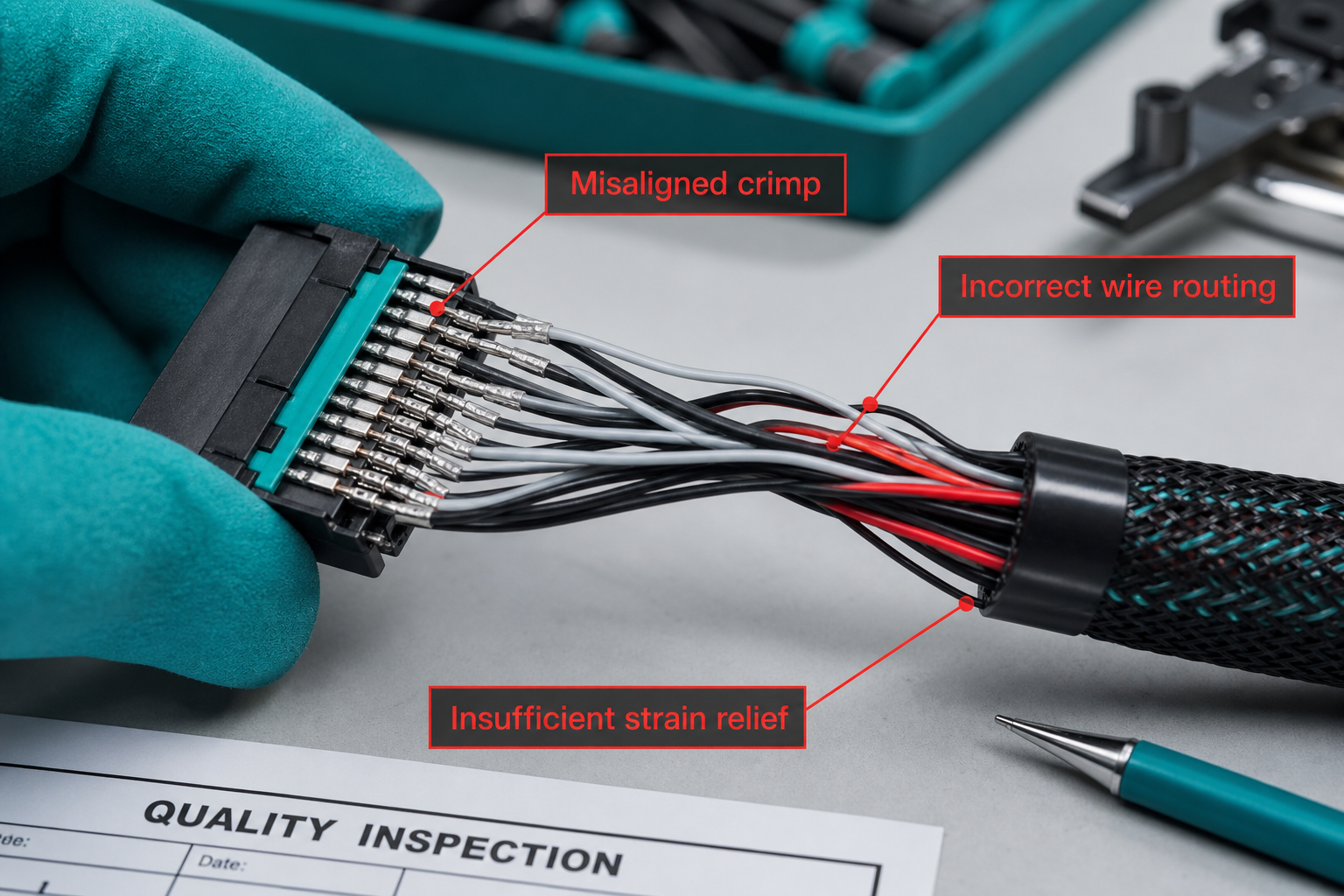
Connector orientation is a DFM variable, not just a mechanical preference. Mirroring a connector may solve a cabinet exit but can make crimp verification impossible. If the program requires pull-test or crimp-height sampling, the drawing should show how that check occurs without disassembling the finished housing.
Where termination quality depends on component-supplier controls, buyers should align the assembly DFM review with the evidence expected in the terminal supplier checklist: approved tooling, sample pull-test records, and change notification before a contact or barrel change affects the build.
Where can poka-yoke and mistake-proofing reduce assembly errors?
Poka-yoke features make the correct build easier to perform and the incorrect build harder to hide. For cable assemblies, mistake-proofing often starts with connector keying, unique pin counts, asymmetric housings, and physically distinct lengths between similar branches. Color alone is weak when multiple wires share the same gauge and insulation color under plant lighting.
Useful mistake-proofing fields to define during DFM include:
- Unique branch length where feasible so reversed branches are obvious.
- Consistent label placement relative to the connector key.
- Separate bagging or staging for left/right or male/female ends that look similar.
- A defined wire fan-out order before housing closure.
- Explicit “do not mate until tested” breakout or test-tail requirement where the process needs it.
These features belong in the controlled drawing or build notes, not in verbal tribal knowledge. A DFM review should ask whether an inexperienced assembler could wire the harness incorrectly without immediately noticing the error. If the answer is yes, the design still needs a poka-yoke improvement.
DFM should confirm that the assembly can be held, routed, and tested on the intended bench or fixture. A design that is possible on a prototype table may fail when the buyer expects a flat-board build, a nail-board process, or a molded fixture for repeat production. Review whether tie points, clamp locations, and connector tails conflict with the fixture surface.
Tooling access extends beyond crimp tools. Heat guns, shrink ovens, shield termination tools, insertion aids, torque tools for backshells, and test probes all need physical space. Inspection access is equally important: if a visual check for wire position, label legibility, or heat-shrink melt pattern is required, the drawing must leave a viewing window before final tie or overwrap.
Rework access is a manufacturability feature too. Even a good process occasionally needs a localized correction. Ask whether a single branch can be replaced or a connector re-terminated without scrapping the full assembly. If not, the buyer should understand that field service or supplier rework will be expensive and plan acceptance and pilot quantities accordingly.
What pre-production review checkpoints catch DFM gaps early?
Use a staged review rather than one final sign-off. A practical sequence is:
- Drawing walk-through — engineering, manufacturing, quality, and sourcing review the specification and build order together.
- Component fit review — confirm connector, terminal, cable, and accessory parts match the drawing and mating condition.
- Prototype or first-article build — build the shortest representative version or full pilot quantity defined by the program.
- Test and workmanship review — compare results to the named acceptance plan or applicable workmanship class such as IPC/WHMA-A-620 where used by the program.
- Production release note — record approved revision, tooling, build order, and any restricted conditions for the supplier.
A pilot build should be triggered when the design introduces a new connector family, a new shield termination method, a new bend envelope, a new label system, or a new test limit. It should also be triggered when the buyer changes volume enough to move from bench assembly to fixture-assisted production. TE Connectivity’s harness and assembly application material reinforces that validation planning belongs with the design decision, not after production starts.
Document every DFM change. A revised bend zone, connector orientation, label rule, or build-traveler step should carry a revision note so the assembly supplier does not mix pre-DFM and post-DFM builds in the same lot.
Which ZUCH connector and terminal routes support the RFQ, and what should buyers send?
DFM often exposes unresolved connector or terminal questions before the harness drawing is frozen. ZUCH’s live site presents connector product routes and terminal product routes for buyers comparing interface components that may appear on the assembly drawing. Those routes support component discovery and documentation review; they do not indicate that ZUCH provides harness DFM services or builds finished cable assemblies.
When DFM review confirms the interface but the buyer still needs item-level documentation, use the live product catalogue to narrow the family and then request the applicable drawing or sample for mating and termination review. Combine that with the specification checklist so the assembly supplier receives a complete release basis.
RFQ inputs to send
- Controlled drawing, revision, and proposed build order.
- Bend-radius limits, routing envelope, and strain-relief method.
- Connector and terminal part numbers, orientation, and mating condition.
- Termination method, tooling access notes, and required process evidence.
- Poka-yoke features: keying, labels, lengths, and staging rules.
- Fixture, inspection, and test-access requirements.
- Pilot quantity, acceptance criteria, traceability, and change-control rules.
Fit Boundary
This DFM guide fits teams that can still change the drawing, BOM, or build notes before production release. It is not a substitute for a customer-specific qualification procedure, a regulated-program approval, or supplier-specific process certification. A connector or terminal catalogue entry is a component route, not proof that a finished custom cable assembly is manufacturable in the buyer’s intended volume and acceptance system.
To request connector or terminal documentation while the DFM review is open, use ZUCH’s sample request route or contact page and provide the controlled drawing inputs above. That keeps the inquiry at the component level while the buyer finalizes the assembly design with its chosen assembly supplier.

Run a DFM gate before tooling, fixtures or pilot production are released
The most useful DFM review is a short, cross-functional gate between the drawing and the first build. Include design, manufacturing, quality and test owners, and review the actual assembly sequence instead of looking only at the finished harness.
| DFM gate |
Review question |
Action if the answer is unclear |
| Routing |
Can the cable reach every branch without violating bend or service-loop limits? |
Add controlled bend zones and reference dimensions to the drawing |
| Termination |
Can the operator access the contact, tool and inspection point in the intended sequence? |
Change orientation, fixture access or assembly order before tooling |
| Mistake-proofing |
Can a wrong connector, branch or orientation be physically prevented or quickly detected? |
Add keying, fixtures, visual marks or a point-to-point check |
| Test access |
Can continuity, insulation or functional checks be performed without damaging the assembly? |
Define test points and acceptance records before pilot build |
| Pilot learning |
Which assumptions need a first-piece or pilot build to confirm? |
Record the open risk, owner and release criterion |
DFM is not a promise that every assembly will be cheaper. It is a way to move avoidable ambiguity into the design review, where a connector orientation or fixture change is usually easier to make than a production rework instruction.
Keep the review output tied to a revision. The released drawing should show the decisions that affect build sequence, inspection and service, while unresolved items remain visible with an owner and due date.
A workmanship standard does not replace a manufacturability review
IPC/WHMA-A-620 can define materials, methods and acceptance criteria, but it does not make an impractical routing, termination or fixture design manufacturable. Review bend radius, strip/crimp access, branch geometry, strain relief, labeling, test access and tolerance stack-up before tooling and first articles. Record approved DFM changes against the drawing and BOM revision.
FAQ
What is the first DFM question for a custom cable assembly?
Ask whether the assembly can be built, inspected and tested in the intended sequence without violating routing, bend, termination or access limits. If the sequence is unclear, the design is not ready for tooling release.
When is a pilot build justified for a cable assembly?
Use a pilot when the routing, termination, fixture, test or mistake-proofing assumptions are new or high risk. Define what the pilot must demonstrate before the production drawing is released.
How does DFM reduce cable assembly rework?
It exposes ambiguous dimensions, inaccessible terminations, wrong-orientation risks and missing test access before volume production. The gain comes from changing the design or process while the cost of change is still low.
What is DFM for a custom cable assembly?
It is a structured review of whether the specified harness can be routed, terminated, dressed, labeled, inspected, and tested with acceptable rework risk before production release.
Why does bend radius matter?
Bends tighter than the cable allows can damage insulation or shield performance and may not appear in a simple continuity test until the assembly is installed or flexed in service.
What causes rework most often?
Common drivers include inaccessible terminations, wrong build sequence, inadequate strain relief, ambiguous wire identification, and unreachable test or inspection points.
How does poka-yoke help?
Keyed connectors, distinct branch lengths, controlled label placement, and clear staging rules make incorrect wiring harder to perform and easier to detect before shipment.
What should be reviewed before production?
Review bend radius, termination access, shield dressing sequence, mistake-proofing features, fixture and test access, the acceptance plan, and the need for a pilot or first-article build.
How do you check termination access during design review?
Walk the build step by step and confirm tool, hand, and visual clearance for each contact before housing closure, tie points, or heat-shrink capture the area.
When is a pilot build needed?
Use a pilot when the design introduces a new interface, shield method, routing envelope, label system, test limit, or production method, or when volume will move to fixture-assisted build.
Key takeaway
DFM earns its value before tooling and volume production. Review routing, termination access, mistake-proofing, fixtures and test access in one controlled gate, then carry the decisions into the released drawing and pilot plan.
References
 Zhejiang ZUCH Technology Co., Ltd.