PCB Header Current Rating: Why Temperature Rise Matters More Than the Datasheet Number
PCB Header Current Rating: Why Temperature Rise Matters More Than the Datasheet Number
A header’s usable current is set by temperature rise in your application, not by the headline catalogue number. Read the rating’s conditions, then verify the real contact grouping and ambient.
Contents
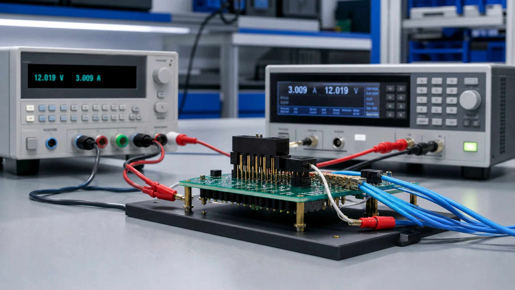
A published current figure describes a specific test arrangement: a defined contact count under load, wire or trace sizes, ambient temperature and an allowed temperature rise. Change any of those conditions and the number no longer applies directly.
| Rating element |
What the catalogue states |
What your application changes |
| Loaded contacts |
Defined pattern in the test |
Real grouping and return paths |
| Conductors |
Test wire or trace sizes |
Actual trace cross-sections |
| Thermal context |
Open-air ambient and rise limit |
Enclosure, stacking and local heating |
Part 2. Why does temperature rise matter more than the headline number?
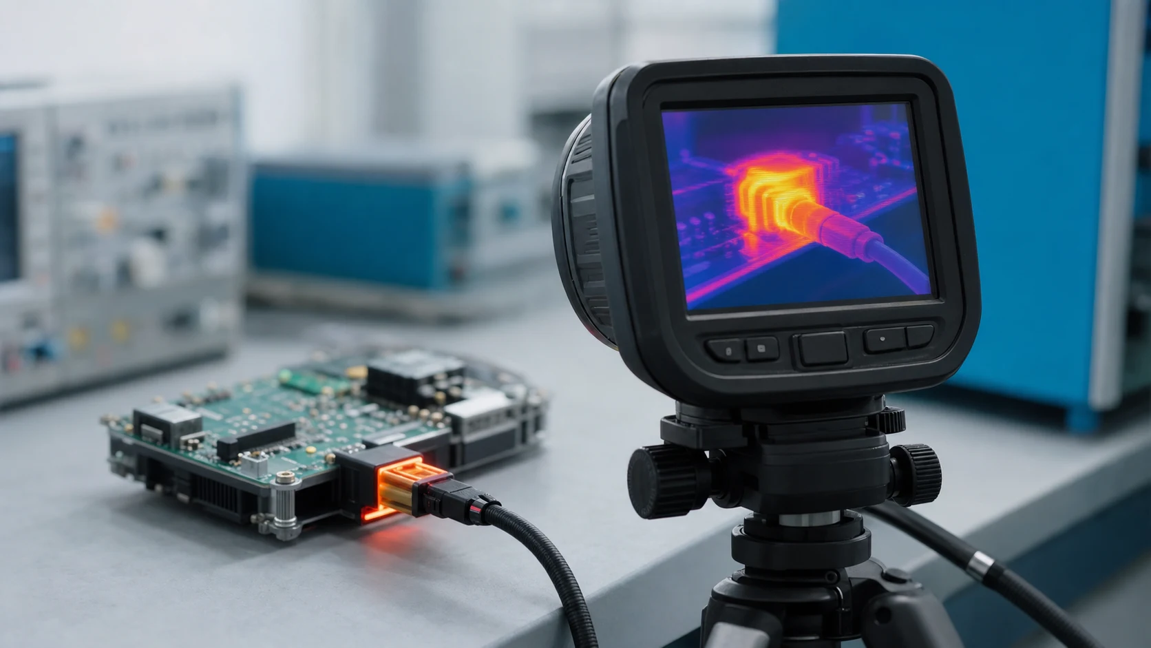
Heat at the contact interface drives relaxation, plating degradation and neighbouring component stress long before an abrupt failure. Interfaces are commonly assessed against an agreed rise limit above ambient, which is why the same part supports different currents in different designs.
Contacts heat their neighbours, so a fully loaded header runs hotter than a single energized contact at the same current. Establish how many positions carry load simultaneously and how return paths are distributed before trusting any per-contact figure. For a related technical reference, see PCB Header Pitch Selection: Matching Current, Density and Assembly Process. For a related technical reference, see PCB Power Connector.
Part 4. Which application factors reduce usable current?
Elevated ambient, enclosed housings, small trace cross-sections, long duty cycles and stacked boards all push the interface toward its rise limit sooner. List these factors explicitly in the design review so the derating logic is visible and repeatable.
| Factor |
Direction of effect |
Review action |
| Higher ambient |
Less allowable rise budget |
State worst-case ambient |
| Full-position loading |
Higher interface temperature |
Test the real load pattern |
| Thin traces |
Extra heating at pads |
Align layout with duty |
Part 5. How should a temperature-rise check be planned?
Test the real footprint, trace layout, loaded positions and enclosure condition, and measure at the agreed points until readings stabilise. Define pass limits, instruments and records with the acceptance owner before the test starts.
Important: General guidance cannot approve a specific design or lot. This is a source-note application of the IPC and TE Connectivity references listed below; apply it through your controlled drawing and acceptance plan.
Part 6. What evidence belongs in the release file?
Keep the rating’s stated conditions, your application assumptions, the rise measurements and the approved margins together. That file lets a later current increase or layout change be re-checked quickly instead of re-argued.
Part 7. Which ZUCH route supports a current-rating inquiry?
Use ZUCH’s PCB Header category and the live product catalogue to identify relevant connector, terminal or housing component families. These are discovery routes only and do not demonstrate that a specific configuration is approved for your application.
RFQ inputs
- Electrical duty per contact, load pattern and worst-case ambient.
- Board layout context: traces, vias, stacking and enclosure condition.
- Agreed temperature-rise limit, test method and acceptance records.
- Samples and documentation needed for the release file.
Fit Boundary
This guide supports engineering and sourcing discussion; it cannot replace programme-specific validation, market requirements, or an approval record. Use ZUCH’s sample request route or contact page for controlled component documentation and samples.

FAQ
What does the current rating on a PCB header mean?
It reports the current the part carried in a defined test setup within an allowed temperature rise; it is an input, not an application approval.
Why do two designs get different usable currents from one header?
Because grouping, traces, ambient and enclosure differ, so each design reaches the rise limit at a different current.
What is a temperature-rise check?
A measurement of contact-area temperature above ambient under the real load pattern, compared with an agreed limit.
Do all contacts in a header share current equally?
Not automatically. Path resistance and layout decide sharing, so parallel-contact schemes need their own review.
When should derating be applied?
Whenever application conditions are harsher than the rating’s stated test conditions, which is the common case in enclosed products.
Can plating choice change thermal behaviour?
Contact finish influences interface resistance and durability, so confirm the finish assumed by the rating matches the part you buy.
What should buyers request in a current-rating RFQ?
The rating conditions, supporting test context, samples for a rise check, and documentation that matches your acceptance plan.
References
 Zhejiang ZUCH Technology Co., Ltd.