Terminal Block Enclosure Design: Clearance, Creepage and Wire Entry Considerations
Terminal Block Enclosure Design: Clearance, Creepage and Wire Entry Considerations
Treat the terminal block enclosure as part of the electrical interface, not merely a box around it. Clearance, creepage, conductor entry, materials, and service access must be reviewed in the controlled application.
Contents
Part 1. Define the enclosure interface
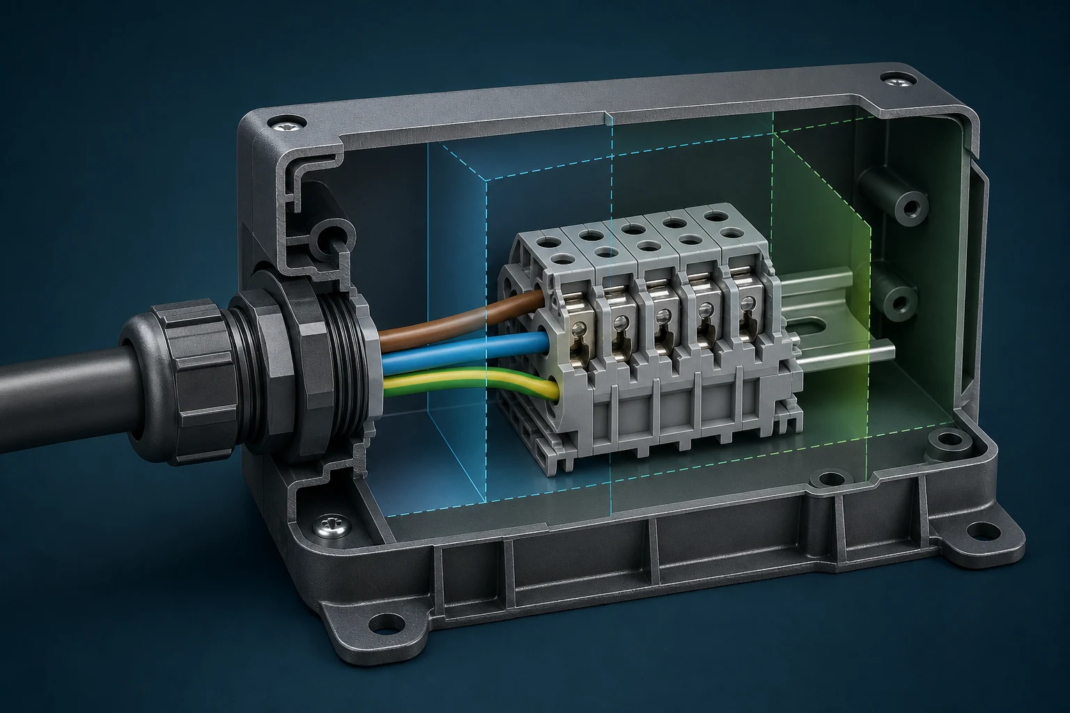
An enclosure review starts with the actual interface: terminal arrangement, conductors, insulating surfaces, metalwork, covers, cable entry, and the conditions around the equipment. Measuring the terminal alone does not establish whether the installed geometry supports the intended insulation coordination or service procedure.
| Design input |
Questions to resolve |
Record to control |
| Electrical interface |
What voltages, circuits, and separation functions are present? |
Schematic and insulation-coordination requirements |
| Physical envelope |
Where are walls, covers, metal parts, and adjacent interfaces? |
Controlled layout and dimensional drawing |
| Installation method |
How do wires enter, bend, terminate, and receive support? |
Wiring instructions and assembly sequence |
Part 2. Separate clearance from creepage
Measure clearance through air between conductive parts, and measure creepage along the shortest insulating surface path. They are related but not interchangeable. A wall, rib, slot, contamination path, or surface material can change the creepage path without changing the straight-line air distance.
IEC 60664-1 provides an insulation-coordination framework, but the selected requirements depend on the applicable equipment context. Use the controlled standard, product documentation, and system requirements rather than treating a general explanation as a final dimension.
Part 3. Connect insulation coordination to conditions
Geometry is only one input. Working voltage, transients, overvoltage category where applicable, pollution conditions, altitude, material grouping, and the intended insulation function can affect the evaluation route. Keep the assumptions visible so a late material or enclosure change triggers review instead of silently changing the design basis. For a related technical reference, see Energy Storage Connector Creepage and Clearance: Design Rules for High Voltage.
| Change trigger |
Why it needs review |
Example controlled response |
| New enclosure material |
Surface behavior can alter the path being considered |
Recheck the documented insulation assumptions |
| Revised cable entry |
Bend, support, and wire route can move conductors |
Reissue the layout and assembly instructions |
| Added adjacent circuit |
The separation relationship may change |
Review the updated circuit and physical arrangement |
Part 4. Design the wire-entry route
Wire entry should show the permitted conductor range, preparation method, entry angle, bend allowance, and route to the nearest restraint. A cable gland can manage entry through an enclosure wall, but it does not automatically define the conductor support or the load path at the terminal. Keep sealing, cable retention, and terminal termination as separate design checks. For a related technical reference, see Terminal Blocks vs Plug-In Connectors: Selecting a Serviceable Power Connection.
Choose entry direction with the installed cover and tool path in mind. The route should avoid forcing a conductor across an insulating barrier, pulling it against a terminal, or preventing a technician from seeing the required insertion and retention features.
Part 5. Preserve installation and service access
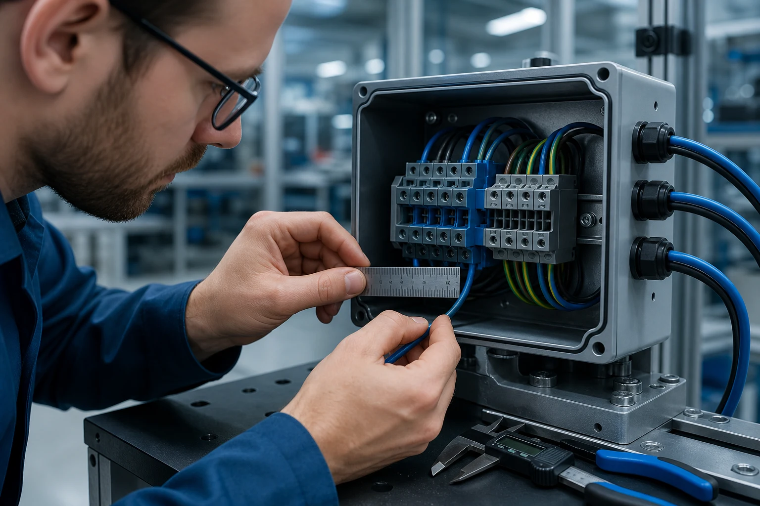
A compact arrangement is not serviceable if the installer cannot insert the conductor, operate the termination method, inspect it, and refit the cover without damaging adjacent wiring. Reserve space for fingers, tools, bend radius, cable motion, and any required verification step.
For supplier-review context, see the terminal supplier quality control checklist. It supports questions about controlled evidence but does not establish enclosure compliance.
An RFQ should include the controlled interface drawing, circuit separation intent, enclosure dimensions and material, wire and cable data, entry hardware, expected environment, and required records. Ask for exact product documentation and samples tied to the quoted configuration. This avoids comparing component families that use different assumptions.
The final release should also name the change triggers: terminal substitution, enclosure material change, revised cable entry, new circuit, or altered environment. Each can require review of the interface rather than a simple purchasing substitution.
Part 7. Where can a terminal inquiry begin?
Use the ZUCH terminal product route and the product catalogue to begin controlled component discovery. These routes do not demonstrate that a terminal block enclosure configuration is approved for a finished product.
RFQ inputs
- Controlled layout, circuit separation intent, and relevant operating conditions.
- Terminal interface, conductor range, preparation method, cable entry, and support constraints.
- Enclosure material, geometry, cover, service-access, and environmental requirements.
- Samples, documentation, validation evidence, records, and change-control needs.
Fit Boundary
This guide supports engineering and sourcing discussions, not an insulation-coordination calculation or equipment approval. Use the sample request route or contact page for a controlled component inquiry.
FAQ
What is the difference between clearance and creepage?
Clearance is measured through air; creepage follows the shortest path along an insulating surface. Both must be considered in the actual arrangement.
Can a terminal block enclosure be sized from terminal pitch alone?
No. The enclosure also needs the controlled conductor route, entry hardware, adjacent circuits, covers, materials, service space, and required separation relationships.
Why does wire entry direction matter?
It affects bend space, tool access, conductor load, visibility of the termination, and whether the installed route conflicts with walls or covers.
Do cable glands replace terminal strain relief?
No. A gland and a terminal can have different functions. Review the cable-entry retention and the conductor load path at the terminal separately.
How should enclosure material be considered?
Record the actual material and conditions relevant to the design requirements, then review changes through the controlled insulation-coordination process.
What information should be on the drawing?
Include interface geometry, circuit separation intent, terminal positions, cable entry, conductor routing, materials, covers, dimensions, service access, and revision control.
What should buyers request for an enclosure-interface RFQ?
Provide controlled drawings and conditions, then request exact product documentation, samples, required evidence, records, and change-control commitments for the quoted configuration.
References
 Zhejiang ZUCH Technology Co., Ltd.