Terminal Blocks vs Plug-In Connectors: Selecting a Serviceable Power Connection
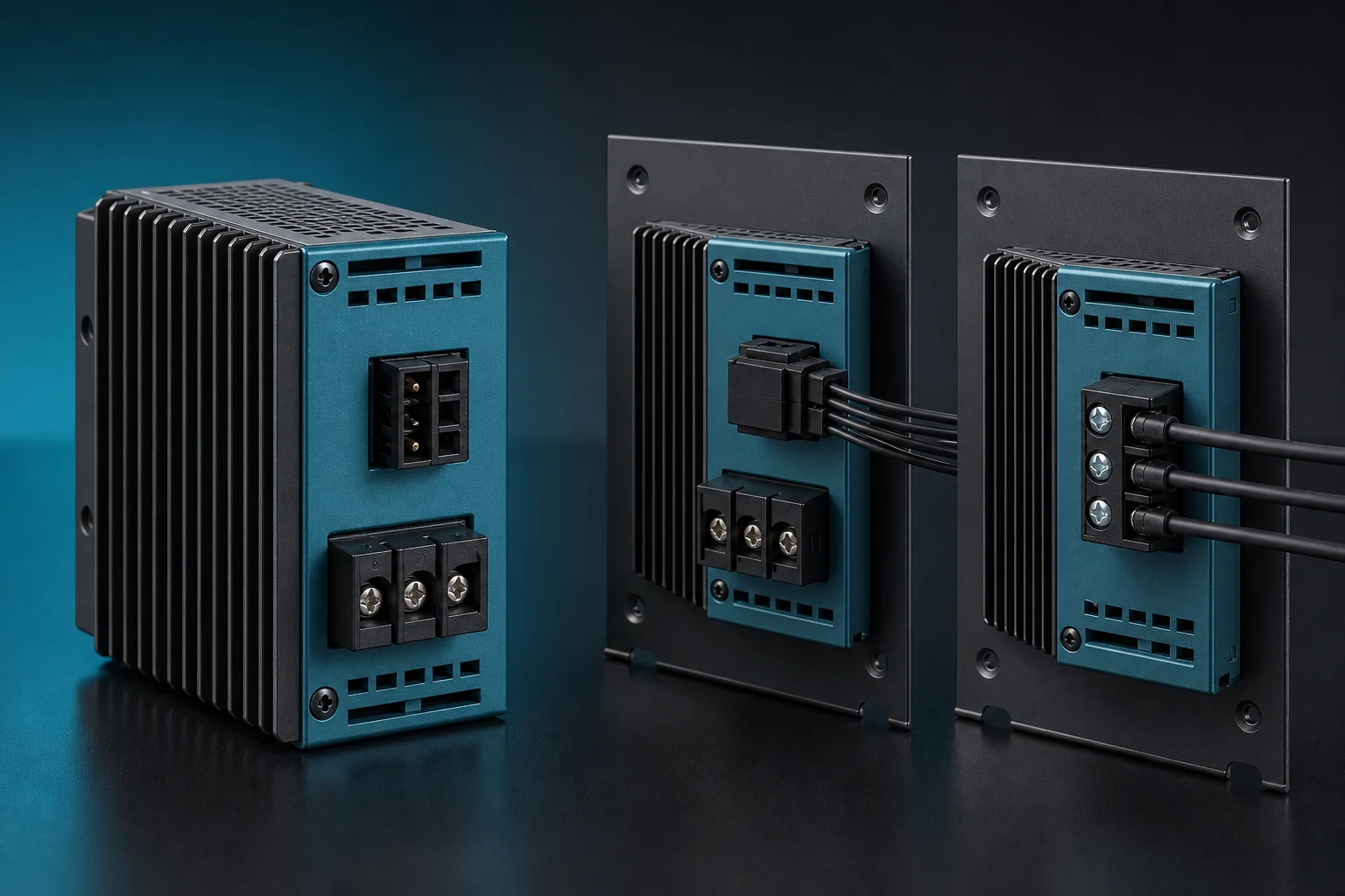
A terminal block and a plug-in connector are not mutually exclusive choices: a pluggable terminal block combines a wire clamp with a separable plug and header. Missing that option can make a maintenance comparison unnecessarily narrow. The useful question is which wiring must remain in place when a module is replaced, and whether the installed connection can be reached, isolated and checked. This guide compares fixed wiring, pluggable terminal blocks and harness connectors against those service tasks.
The short answer is to choose the disconnect architecture separately from the wire-termination method. Screw and spring describe how the conductor is held; fixed and pluggable describe whether an interface separates. Same Sky’s terminal block guide includes pluggable arrangements. Neither a clamp style nor a plug establishes a universal current rating or permission to disconnect under load.
Contents
What must the power connection allow a technician to service?
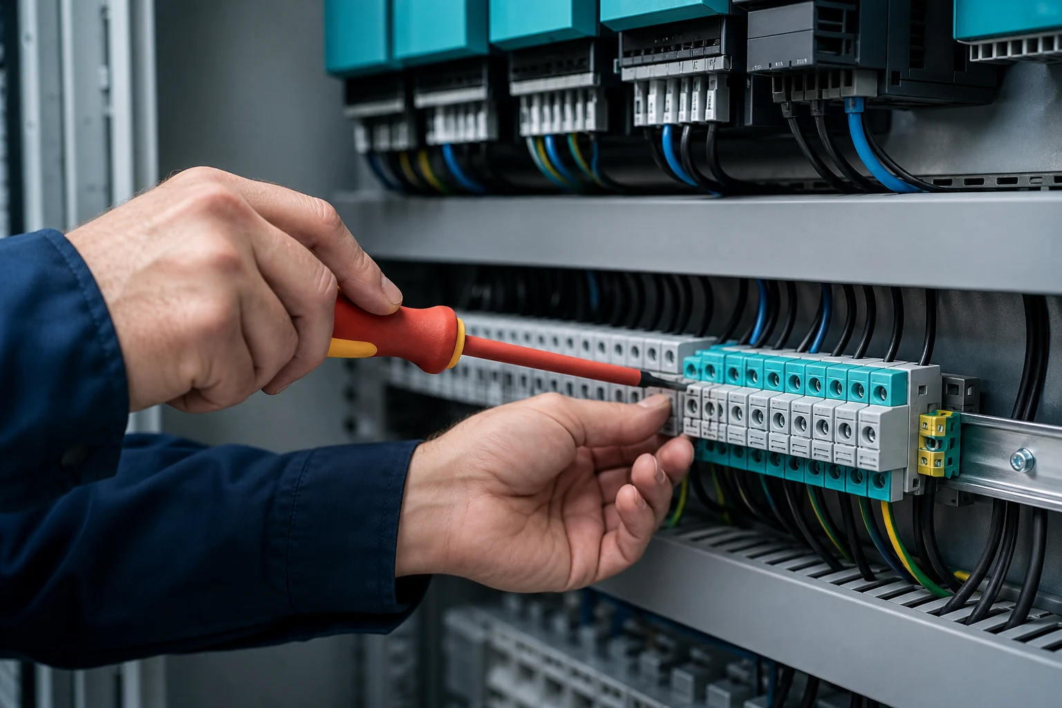
The first question is not which form factor looks smaller. Establish who terminates the wires, whether a field technician must disconnect a module, how often that operation is expected, and what evidence is required before the assembly is released. A fixed terminal block retains individual conductors at a defined wiring point. A pluggable terminal block adds a separable interface while leaving its wire terminations in the removable plug. A harness connector provides another form of mating interface, often with separately specified contacts and housings. Check terminal block clearance, creepage and wire-entry space in the installed enclosure rather than from the connector body alone.
| Review area |
Terminal-block question |
Plug-in-connector question |
| Installation task |
Who strips, inserts, and tightens or actuates the wire termination? |
Who terminates each side and controls the mating pair? |
| Service event |
Can a technician safely access the individual termination? |
Can the required module be disconnected without disturbing adjacent wiring? |
| Controlled interface |
What conductor and terminal method is specified? |
What keying, retention, mating state, and counterpart are specified? |
How do fixed, pluggable and harness connections differ?
Terminal blocks are commonly selected where individual conductors enter a fixed wiring point and visual access matters. Plug-in connectors are commonly selected where an assembly or module needs a repeatable disconnect interface. Neither description establishes a rating, lifetime, or suitability by itself; those properties belong to the specific product, conductor, application, and installation instructions.
The architecture also changes the failure investigation path. With a fixed terminal point, inspection may focus on conductor preparation, insertion depth, retention method, and the installed terminal. With a separable pair, the review additionally includes mating orientation, latch engagement, keying, contact interface condition, and the specific counterpart.
What steps are needed to disconnect and replace the module?
Map the service motion before choosing a plug-in interface. A connector that is easy to unplug on a bench may be hard to reach after cable routing, covers, adjacent modules, and strain relief are installed. Conversely, repeated access to a fixed terminal can add time and create opportunities to disturb neighboring conductors.
| Service factor |
What to document |
Why it changes the choice |
| Access direction |
Tool clearance, hand clearance, and cover removal steps |
A serviceable interface must remain reachable in the installed assembly |
| Disconnect sequence |
Isolation, unlock, unplug, reconnect, and inspection steps |
The sequence affects safety planning and recovery from a service event |
| Cable support |
Clamp locations, bend allowance, and movement constraints |
Cable load should not be transferred unpredictably into the connection |
Which electrical and environmental limits must be verified?
Do not transfer an electrical value from one connection style to another. The relevant documentation should identify conductor size and construction, temperature conditions, number of energized positions, spacing, enclosure conditions, and the intended connection method. A system-level selection may also require review of transient conditions, vibration, contamination, ingress, and maintenance behavior.
IEC 61984:2008 addresses connectors within its stated safety scope: rated voltages above 50 V up to 1,000 V AC/DC and currents up to 125 A per contact, under its specified applicability conditions. These are scope limits, not ratings for every product. The finished equipment still needs its own applicable requirements, and lower-voltage connections cannot be approved by citing this scope alone.
How much space is needed for wiring and service access?
Wire entry deserves the same attention as the mating face. Define the permitted conductor range, insulation strip length, ferrule or conductor preparation where applicable, entry angle, bend space, and the route to the nearest support point. In a plug-in design, reserve space for the unmating direction and the connector body; in a fixed design, reserve access for the termination tool and inspection.
Keep the enclosure, polarization, and protection requirements in the controlled interface definition; they cannot replace the requirements for this power connection.
What information makes supplier quotations comparable?
An RFQ should make the comparison repeatable. Provide the circuit count, conductor definition, nominal operating conditions, enclosure envelope, service expectations, counterpart details, and required records. Ask suppliers to identify the exact documentation that supports their quoted configuration, rather than accepting an unspecified “equivalent” connection approach.
The purchasing review should separate a product family from the final application. A product route can aid early discovery, while the drawing, samples, applicable requirements, and agreed validation plan determine whether a selected configuration can progress.
What should be requested before approving a connection?
For a component inquiry, provide the circuit, conductor, mating architecture and service constraints alongside the relevant connection components. If the design uses an inline splice instead, assess the wire-joining and service consequences separately. A splice and a separable module interface do not perform the same maintenance task.
Which records should accompany the connection RFQ?
- Controlled drawing, circuit count, mating or termination architecture, and revision.
- Conductor material, size range, preparation method, cable routing, and support plan.
- Electrical, environmental, enclosure, and service conditions that affect the interface.
- Required samples, inspection or validation evidence, records, and change-control expectations.
What can connection samples confirm before production?
Use component samples to check the documented wiring process, access, mating and inspection steps in the installed assembly. A bench sample cannot replace the equipment requirements or demonstrate a lifetime service result by itself.

When is a pluggable terminal block a useful middle option?
Consider it when field wires should remain terminated during module replacement but a separately crimped harness is not the preferred installation method. The clamp type still needs to suit the conductor, and the plug/header pair needs documented keying, retention and electrical limits. TE’s PCB connector overview includes connector families for board-level interfaces; the exact product documents determine whether a quoted terminal system provides the required separable arrangement.
| Architecture |
What remains connected during service? |
What must be checked? |
| Fixed terminal block |
Conductors remain at the fixed point unless individually released |
Tool access, conductor preparation and retermination procedure |
| Pluggable terminal block |
Wires can remain in the removable plug |
Plug/header match, retention, access and clamp instructions |
| Harness connector |
Wires remain in the terminated housing |
Contacts, housing, keying, latch and approved mating pair |
Should screw or spring termination be chosen for the wire?
Keep the clamp decision separate from whether the interface is fixed or pluggable. Compare the documented conductor type and range, preparation, strip length, permitted ferrules, tool access and any torque requirement. Do not apply one tightening value to all screw terminals or assume that every stranded conductor needs the same ferrule. Same Sky distinguishes screw and spring approaches and relates selection to the electrical and mechanical application.
If an installer must work in a narrow enclosure, demonstrate the actual termination operation with the intended wire and tool before finalizing the component. A connection that is compact on a drawing may need additional space to prepare, insert and inspect its conductors.
How can service time be compared without inventing savings?
Use the same installed module, access conditions and safe isolation procedure for each architecture. Record cover removal, cable release, disconnection, replacement, reconnection and inspection separately. Also record whether neighbouring wiring is disturbed. This is a proposed comparison method, not a claim of measured time savings. Choose a pluggable arrangement when it solves the actual replacement task; do not assume that the act of unplugging removes the rest of the service work.
IEC 60512-1:2018 provides a framework for connector tests with detail specifications and defined limits. Use the applicable product and equipment evidence for electrical release. A separable interface must not be treated as a load-break switch unless that operation is explicitly specified and approved.
Frequently asked questions
Is a pluggable terminal block a terminal block or a connector?
It combines both functions: a wire termination in the removable plug and a separable interface to the matching header. Therefore, terminal block versus plug-in connector is not a strict either-or distinction. Compare the actual wiring and service architecture.
Are screw and spring terminals always fixed connections?
No. Screw and spring describe the conductor-clamping method, while fixed or pluggable describes the disconnect arrangement. Select both characteristics from the product documentation and the service task rather than treating them as the same classification.
How much current can a terminal block carry?
There is no universal value. Check the exact part, conductor range, temperature conditions, loading, spacing and installation instructions. A family maximum or the rating of a different conductor configuration cannot be transferred to the installed connection.
Does every stranded wire need a ferrule in a terminal block?
Do not assume one universal preparation rule. Follow the selected terminal's instructions for stranded conductors, permitted ferrules, strip length and tool use. Verify the actual conductor and ferrule combination rather than selecting from wire size alone.
Can a plug-in power connector be unplugged under load?
Only where the exact product and application explicitly allow the intended energized operation. Separability does not establish switching capability. Otherwise, follow the equipment's isolation procedure before disconnecting, then perform the required reconnection checks.
Are plug-in connections always faster to maintain?
No. A plug can leave wire terminations undisturbed, but access, lock operation, cable support, covers, isolation and final inspection still affect the task. Compare the full installed service sequence rather than timing only the unplugging motion.
Conclusion
The serviceable power connection is the one that fits the equipment’s wiring and replacement task. Choose the disconnect arrangement first: a fixed termination, a pluggable terminal block or a harness connector. Then select the wire-clamping or contact method from the permitted conductor and assembly instructions. Check installed access, cable support and electrical conditions before comparing cost or service time. A plug does not automatically shorten the complete maintenance operation, and neither separability nor a catalogue current value permits live disconnection. ZUCH can support an initial component inquiry when the circuit, conductor and service requirements are clear; final acceptance should remain tied to the exact product, equipment requirements and documented verification.
 Zhejiang ZUCH Technology Co., Ltd.