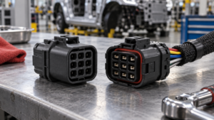
RAST Connectors on Appliance PCBs: Review Layout, Mating, and Retention
A RAST connector layout should be reviewed as part of the appliance PCB, mating interface, cable route, enclosure, and service context. A family name or product image cannot by itself establish fit, retention, or release readiness.
Contents
Part 1. Define the RAST connector layout boundary
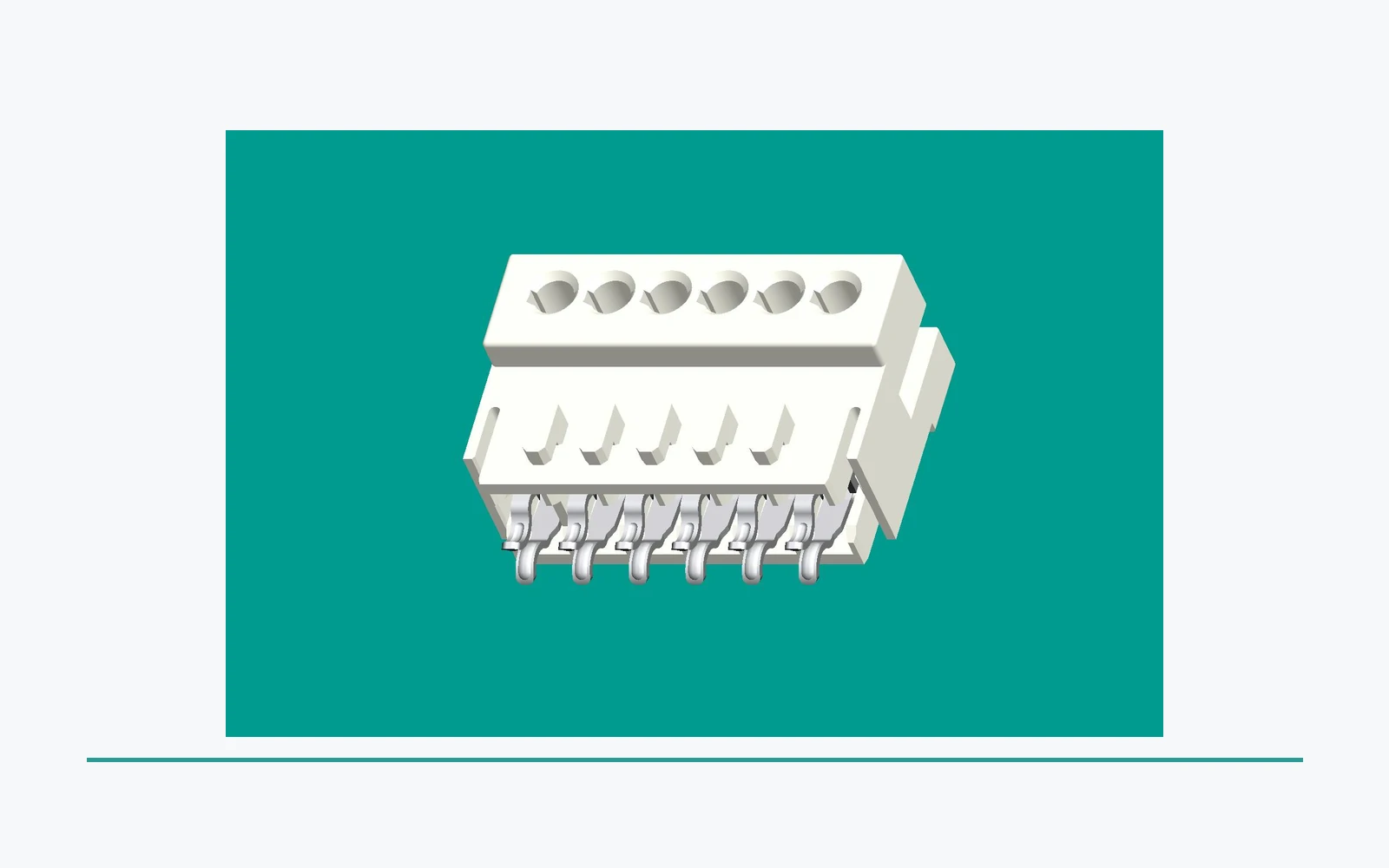
Start from the released connector and mating definitions, the intended PCB location, and the surrounding appliance assembly. The layout review should identify the board envelope, interface orientation, cable exit, nearby components, enclosure boundaries, and access needed for assembly or service.
This approach helps engineering and sourcing discuss the same defined interface. It also prevents a broad product-family description from being used as a substitute for the controlled drawing.
| Layout input |
Why it matters |
Controlled record |
| Footprint and orientation |
Defines where the interface sits on the board |
Current PCB layout and revision |
| Mating relationship |
Identifies the matching connector and engagement direction |
Mating drawing and keying information |
| Assembly envelope |
Shows nearby components and enclosure dependencies |
Board, harness, and housing layout |
Part 2. Reserve the controlled board envelope
Review the released footprint with the height, keep-out, routing, component-clearance, and manufacturing constraints defined for the board. The complete assembly, rather than a connector outline alone, determines the space that needs to be preserved.
Any design-rule values belong to the responsible organization’s controlled documentation. This article identifies selection questions; it does not prescribe PCB dimensions or assembly limits.
Important: A connector footprint that appears to fit on a board view is not evidence that the complete PCB, mating interface, enclosure, and intended assembly conditions have been validated. Source: IEC 61984 connector overview.
Part 3. Review mating direction and retention dependencies
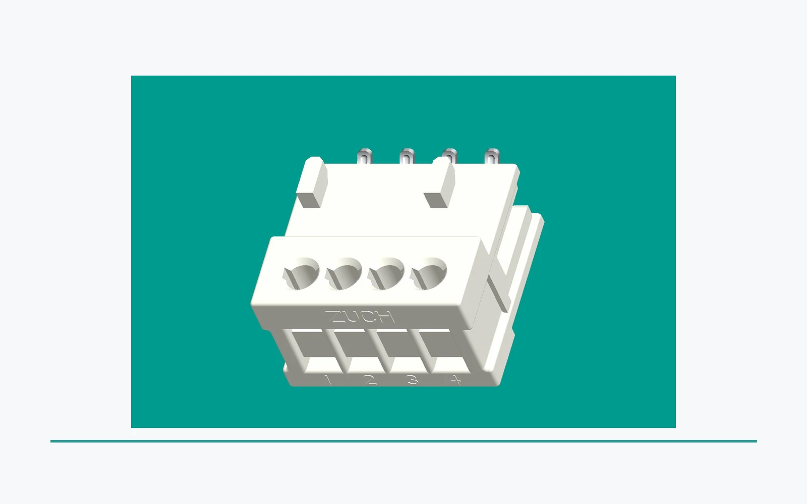
Check the intended mating direction, keying, engagement path, retention feature, and clearances around the released connector system. Retention depends on the complete specified interface and its application conditions, not on a housing image alone.
Document the interface revision and any dependent components. This makes a prototype or supplier response easier to compare with the intended PCB assembly.
Part 4. Include cable routing and service access
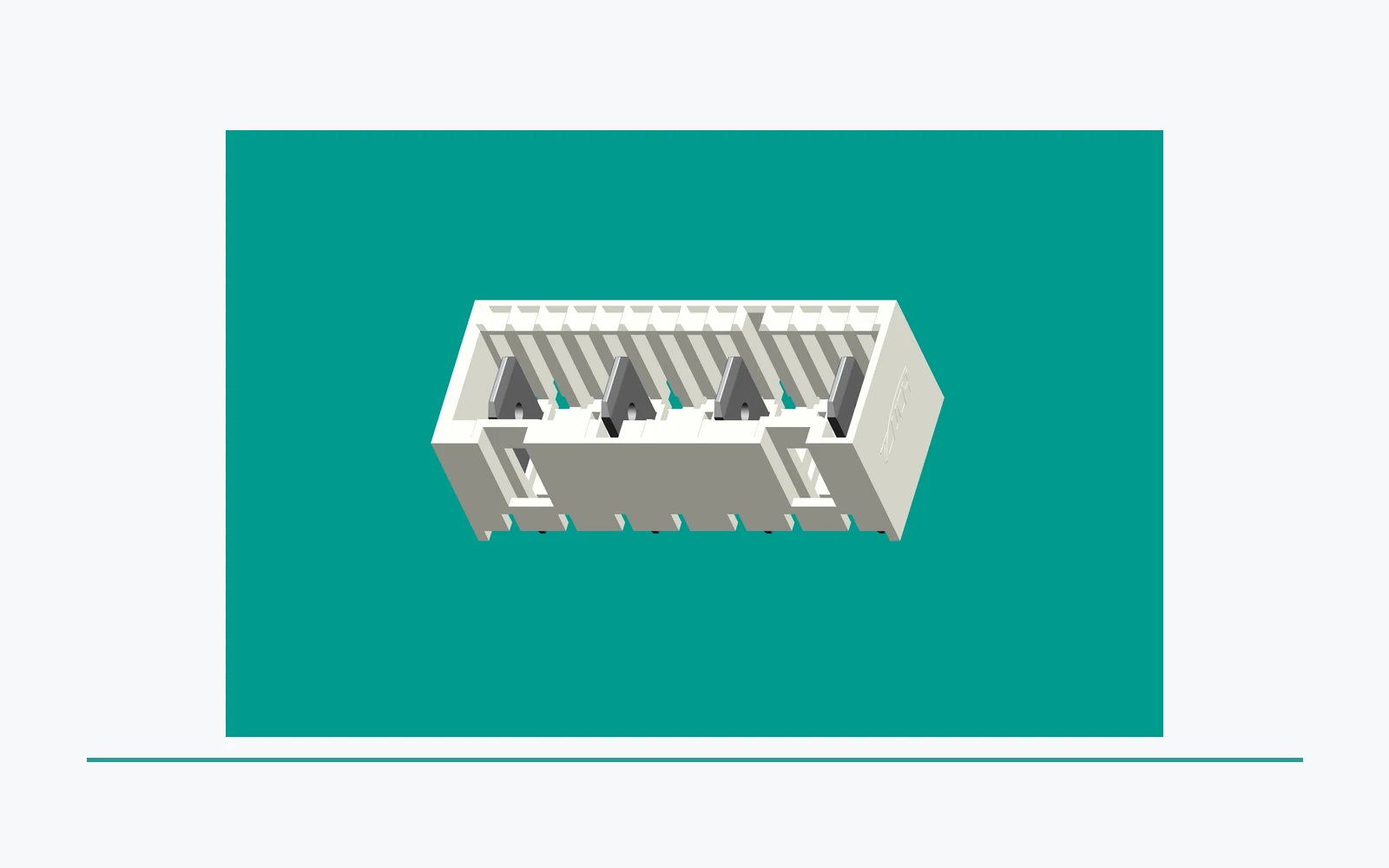
Cable exit direction, bend space, harness support, nearby covers, and service access can all affect a PCB interface. Review them in the installed assembly view, not only in the board CAD view.
This is especially useful where an appliance enclosure limits the path to mate, inspect, or release a connector. The responsible organization must define any controlled service process for the finished equipment.
Send the controlled inputs that allow a supplier response to be compared against the correct interface. The package should identify what is under review rather than assume compatibility from a generic RAST description.
| Inquiry item |
Purpose |
Send with RFQ |
| PCB and mating definition |
Identifies the intended interface |
Footprint, connector, mating drawing, and revision |
| Envelope and routing |
Shows packaging and access constraints |
Board, enclosure, cable exit, and support layout |
| Evidence request |
States program expectations |
Sample objective, requested records, and evaluation needs |
| Change control |
Keeps the inquiry tied to the release basis |
Revision, notification, and traceability expectations |
Part 6. Reopen review when the interface changes
A change to the footprint, mating part, orientation, keying, cable route, enclosure, or intended use can affect the original layout review. Record the difference and route it through responsible engineering before relying on prior evidence.
The same discipline applies when a proposed alternate uses a similar family name. Compare the complete controlled interface, not only the category label.
Part 7. Use ZUCH routes for a controlled RAST connector inquiry
ZUCH’s RAST connectors route lets a buyer locate relevant connector families before the controlled PCB review. It does not confirm board compatibility, retention performance, availability, validation, or approval for a particular appliance.
For a PCB-focused inquiry, send the current layout and mating drawings, board and enclosure envelope, cable routing and access constraints, sample objective, requested records, and change-control requirements through ZUCH’s sample request route. The IDC versus crimp RAST guide covers the related termination-review inputs. For a related technical reference, see Quick-Connectors for Serviceable Assemblies: Review Access and Replacement Inputs. For a related technical reference, see Sealed vs Open Rectangular Connectors: Define Environmental Inputs First.
FAQ
Does a RAST connector family name define PCB fit?
No. Confirm the released footprint, mating interface, orientation, envelope, routing, and program evidence for the intended assembly.
What should be reserved around a connector on a PCB?
Review the controlled footprint, mating path, component and enclosure clearances, cable exit, tooling, and access requirements.
Why does mating direction matter?
It affects keying, engagement path, clearance, cable routing, and the ability to inspect or service the installed assembly.
Does retention depend only on the connector housing?
No. Retention must be considered with the specified mating system, board, enclosure, harness, and application conditions.
Should cable routing be part of PCB review?
Yes. Cable direction, bend space, support, and nearby hardware can affect the connector interface and access.
What should a layout drawing identify?
It should identify the controlled footprint, connector and mating definitions, orientation, relevant envelope, routing constraints, and revision.
What belongs in a RAST connector RFQ?
Provide the current footprint and drawings, mating definition, board and enclosure layout, routing and access limits, sample objective, requested records, and change-control expectations.
References
 Zhejiang ZUCH Technology Co., Ltd.