Zhejiang ZUCH Technology Co., Ltd.
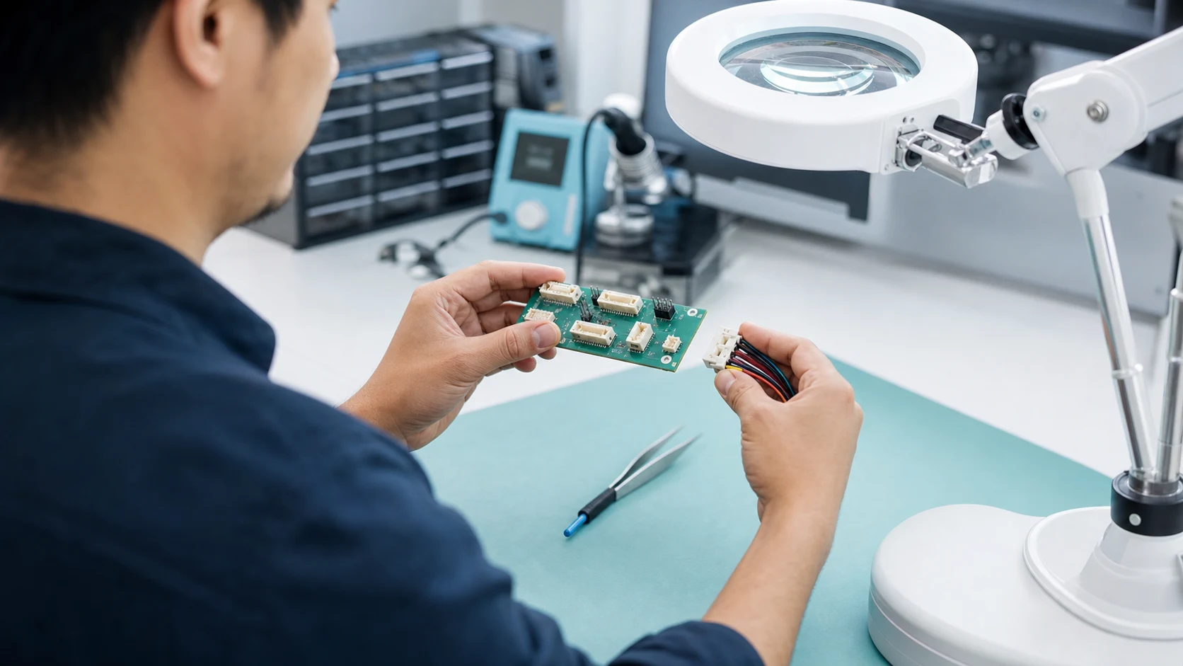
When a controls engineer in Shenzhen encountered intermittent resets on a newly assembled appliance controller, she replaced the wire harness and powered the board again. Within minutes, a light pull on the cable recreated the fault: the header rocked, the contact path opened, and the controller reset. The reversal came from reviewing the footprint, mating system, solder anchoring, and specification; the issue was connector selection and process control, not simply a bad part.
Summary: Reliable PCB interconnection starts by matching signal, power, mechanical, and assembly requirements—not by choosing a familiar outline. IEC 61984 addresses connector safety requirements and tests, while IEC 60512 provides test methods and measurements rather than a blanket product approval. Buyers should first define the circuit current, pitch, mating cycles, board orientation, retention load, and applicable market before selecting a family and validating its own datasheet.
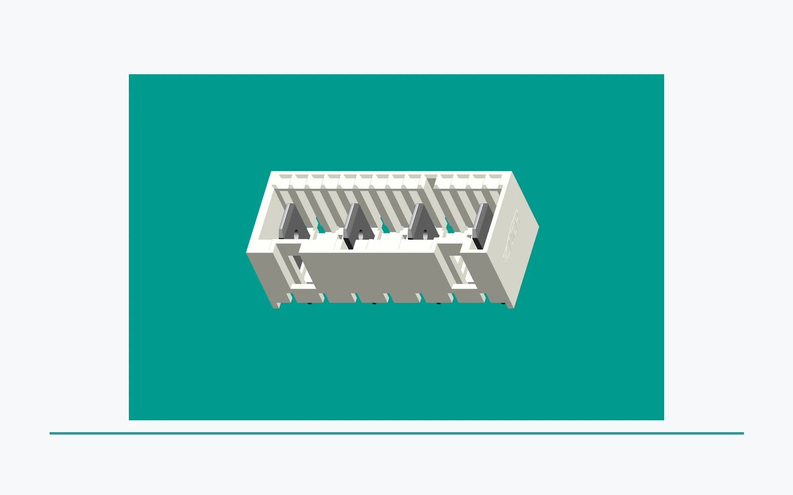
Board-level connectors join a PCB to wires, another PCB, or a serviceable module. Their small footprint can hide lifecycle costs: a mismatch may create assembly rework, intermittent failures, return analysis, or redesign.
How do PCB connector families differ?
The practical starting point is the electrical and mating geometry. The most familiar pair is a header—pins or blades fixed to the PCB—and a receptacle, socket, or housing that mates with it. Depending on the application, the pair may be shrouded and keyed, polarized, locking, or unshrouded for compact internal routing. The term pcb board connector types covers more than pin headers: it also includes wire-to-board housings, board-to-board mezzanine systems, edge interfaces, terminal blocks, and blade-style power connections. For a related technical reference, see What Is a Power Connector?.
Headers, sockets, and terminal interfaces
Pin headers and sockets suit modular low-voltage control boards when pin count, service access, and pitch are controlled. Shrouded headers improve polarization; latching housings define mating behavior. Terminal blocks, spring terminals, crimp systems, and FASTON-style blades suit wire termination where a dense signal array is not the need.
Connector interface safety is not inferred from shape. For teams comparing pcb board connectors, IEC 61984 frames applicable safety requirements and tests, but each part still needs dimensional, material, voltage, current, and environmental documentation. IEC 60512 supplies connector test and measurement methods, including contact-resistance and mechanical or environmental method families.
Which board mounting method fits the assembly and service plan?
Through-hole headers use plated board holes and are often chosen when solder-joint area and mechanical robustness matter. Surface-mount connectors support compact automated layouts, yet retention must be assessed against cable pull, mating force, and board flex. Press-fit compliant pins require controlled hole size, plating, insertion force, and tooling.
Vertical mounting keeps the mating face perpendicular to the board. Right-angle mounting turns the cable exit parallel to it and can improve shallow-enclosure access. Preserve the supplier’s land pattern and keep copper, components, enclosure walls, and cable bend radius out of the mating path.
Mechanical retention is a system property. Locks, locating posts, latches, strain relief, and hold-down tabs can reduce solder-joint stress but do not replace a vibration review. The choice among pcb board connectors should consider cable mass and board flex; agree the IEC 60512 method, severity, conditioning, and pass criteria rather than assume “vibration-proof.”
How should signal and power paths be separated?
Signal interfaces prioritize contact integrity, pin assignment, impedance where relevant, and low-level performance. Power interfaces require thermal and voltage-drop review of the contact system, crimp, trace, vias, mating pair, ambient, enclosure, and duty cycle. A pcb power connector should be specified by the real circuit, not a copied headline figure.
Pitch is centre-to-centre spacing between contacts. Finer pitch increases density but reduces routing room, handling tolerance, and sometimes creepage and clearance margin. A 2.54 mm pitch is common in general-purpose headers; it is not automatically suitable for high-current, high-voltage, contaminated, or vibration-prone designs. Select pitch after electrical spacing, conductor size, assembly capability, and mating ergonomics are understood.
Current capacity cannot be generalized across families. It changes with contact geometry, plating, energized adjacent circuits, wire gauge, temperature rise, mounting, and test condition. Request the individual-family datasheet and validate the finished product where duty cycle or ambient differs; a nominal rating is not a full design calculation.
Comparison of common board-level options
| Interface option | Best-fit performance need | Assembly and service implication | Durability and TCO consideration |
|---|---|---|---|
| Unshrouded header and socket | Compact signal interconnect | Simple placement; control polarization | Low complexity; mis-mating controls may add cost |
| Shrouded, keyed wire-to-board pair | Guided harness connection | Repeatable assembly and service | Housing and latch can reduce field-error risk |
| Right-angle header system | Side-exit cable routing | Allow mating and bend clearance | Retention can reduce service returns |
| Terminal or blade interface | Wire termination or discrete power | Control the crimp or termination process | Tooling and inspection shape TCO |
| Board-to-board connector | Stacked or perpendicular PCBs | Review tolerance stack-up | Can reduce harness labour |
For buyers comparing pcb board connectors, unit price is incomplete. Illustratively, a part that costs less but adds 20 seconds of manual orientation time can lose its saving through labour, fixtures, rework, and return exposure. Compare landed cost and process risk.
Application and dimension matrix
| Application condition | Dimension to define first | Connector direction to investigate | Verification focus |
|---|---|---|---|
| Appliance control PCB | Harness orientation and pitch | Keyed wire-to-board or compatible RAST system | Mating, clearance, applicable IEC 60512 methods |
| Motor or compressor connection | Conductor size, heat, vibration | Blade, terminal, or dedicated motor interface | Datasheet conditions and installed temperature rise |
| Dense control module | Pin count, pitch, board stack | Header/socket or board-to-board | Footprint and insertion-cycle review |
| Power distribution on a board | Current path, voltage, wire gauge | Suitable pcb power connector family | Part-specific current and thermal evidence |
| High-vibration equipment | Retention load and cable relief | Locking or hold-down system | Agreed IEC 60512 method and criteria |
Standards, quality systems, and defensible claims
IEC 61984 addresses connector safety requirements and tests within its scope. It is not a shortcut around product engineering: destination market, voltage, intended use, and part documentation determine what else applies.
IEC 60512 is a series of test and measurement methods for connectors for electronic equipment, not a product certificate. Specifications should identify methods, sequence, severity, conditioning, and acceptance values. Unsupported qualification, current, endurance, or compliance claims can delay approvals and create commercial exposure.
IATF 16949 is an automotive quality-management-system framework for organizations involved in automotive production and relevant service parts. It does not certify connector electrical performance. Automotive buyers still need customer requirements, part validation, traceability, and component documentation.
Selection actions for engineering and procurement
- Write the mating architecture first: circuit count, header or receptacle role, polarization, latch behavior, orientation, service access, and pcb board connector types considered.
- Model the full electrical path, then obtain the specific connector family’s datasheet for voltage, current, temperature, material, and test conditions.
- Release the supplier-recommended PCB footprint into the layout and review keep-outs, strain relief, solder process, and tolerance stack-up before tooling.
- Turn field conditions into a verification plan: vibration, mating cycles, contamination, temperature, pull load, and applicable IEC 60512 methods.
- Qualify the sourcing route with samples, drawing revision control, change notification, and documented acceptance criteria.
For projects needing rectangular connectors, RAST 5.0/2.5 interfaces, FASTON terminals, connecting terminals, solderless terminals, motor/compressor connectors, or ring and spade terminals, ZUCH can be assessed as a connector-system sourcing option. Founded in 1994, the manufacturer can be engaged around the drawing, family documentation, test discussion, and production-fit questions that a controlled procurement process requires. For a related technical reference, see Rectangular Connector Types.
Frequently asked questions
What are the most common PCB connector types?
Common pcb board connector types include pin headers and sockets, shrouded wire-to-board pairs, board-to-board connectors, terminal blocks, and blade or terminal interfaces. The best option depends on the circuit, enclosure, harness, and service model; a familiar header is not automatically the lowest-risk choice.
What is the difference between a PCB header and a socket?
A PCB header is normally the fixed board-side component with pins or blades, while a socket or receptacle is the mating component that receives them. Either side can be integrated into a larger connector system, so confirm the supplier’s terminology, keying, and drawing before assigning a bill-of-material item.
How do I choose a PCB connector pin pitch?
Choose pitch by balancing contact count, routing space, voltage-related spacing, wire size, assembly tolerance, and handling. Start from the electrical and mechanical constraints, then use the selected family’s recommended footprint instead of stretching a generic pattern to fit.
Which PCB connectors carry the most current?
There is no defensible universal winner: a pcb power connector must be evaluated by its specific contact geometry, conductor, energized positions, temperature rise, and test condition. Request the individual family datasheet and assess the complete installed path; do not infer capacity from pitch or housing size.
Can PCB connectors be mounted at right angles?
Yes. Right-angle headers and receptacles route the mating interface parallel to the PCB and are widely used where enclosure depth or cable access makes vertical mating impractical. Confirm cable bend radius, neighboring component clearance, and the connector’s retention features in the actual enclosure.
How do I stop a PCB connector from loosening during vibration?
Use a connector system with appropriate polarization, latch or lock, board hold-downs, and harness strain relief, then validate the installed assembly. Agree a relevant IEC 60512 test method and severity with the supplier, because the board, cable mass, mounting, and environment determine the real risk.
References and the next sourcing conversation
- International Electrotechnical Commission (IEC)
- IEC 61984: Connectors — Safety requirements and tests
- IATF 16949 global oversight information
The durable connector decision is made at the interface between circuit, mechanics, assembly, and evidence—not at the thumbnail in a catalogue. Buyers evaluating PCB headers, RAST connector systems, or the wider connector range can bring their application details to ZUCH for a documentation-led review. For the complete product category and a clear contact path, visit ZUCH products.