Zhejiang ZUCH Technology Co., Ltd.
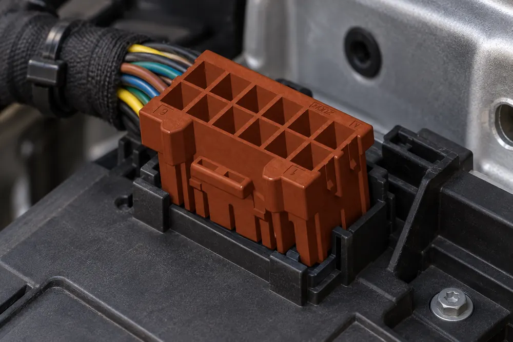
When a harness engineer in Munich plugged a replacement connector into a body-control prototype, the shell appeared to seat but two circuits stayed open; the root cause was a mismatched pin layout and terminal family, not a defective connector.
Summary: A 16-pin automotive connector fits only when the housing geometry, keying, latch, cavity numbering, mating half, terminals, wire range, and electrical assignment all agree. Do not approve a part from pin count or a photograph alone. Compare controlled drawings, verify a complete mating pair, then test continuity and terminal retention on a sample harness. SAE USCAR-2 provides a useful automotive connector-system performance framework, while IEC 61984 addresses connector safety requirements and tests within its scope. Treat fitment as an interface-validation task before production release.
Sixteen positions are often used where a harness combines diagnostics, body electronics, sensors, actuators, communication, power, and ground. That mixture makes an apparently minor difference—such as mirrored numbering, a changed key, or a smaller crimp range—capable of creating a nonfunctional or unsafe assembly. The following checks give purchasing, design, and quality teams a repeatable way to determine whether a 16 pin automotive connector belongs in the intended vehicle wiring.
What belongs in a controlled fitment record for a 16-pin connector?
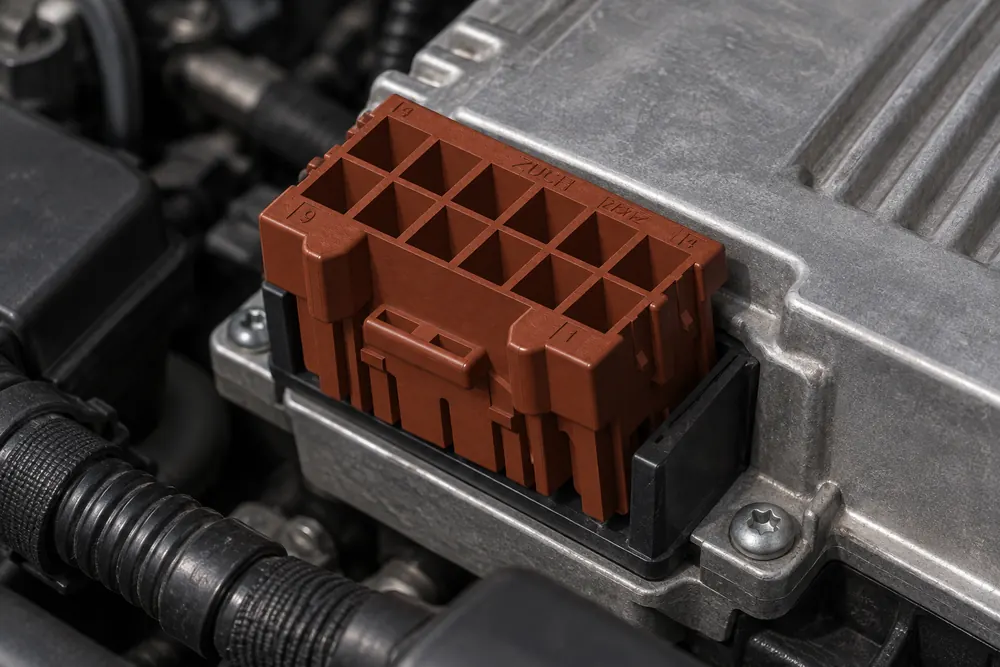
Begin with the vehicle or equipment drawing, not a marketplace listing. Record the connector family, exact part reference, cavity count, row arrangement, polarization key, latch side, mounting features, and mating direction. A 16-position shell can have several key codes, and a connector with the same outside dimensions may use a different internal cavity sequence.
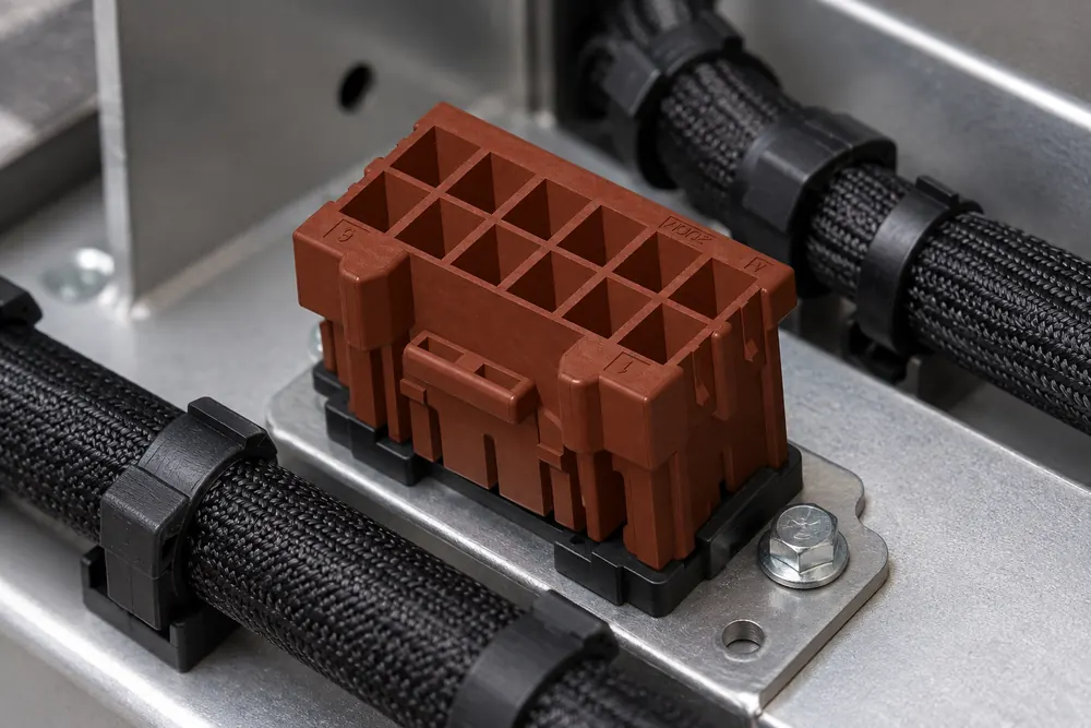
Capture the mating interface as a pair: plug, receptacle, header or bulkhead half, terminal gender, and any backshell or CPA (connector-position assurance) component. Measure the installed envelope, including bracket clearance, cable exit, bend radius, and service access. A bench fit is not proof that the connector will clear a panel, clip, heat shield, or adjacent harness in the vehicle.
Build a pin map that lists cavity number, circuit name, wire color or identifier, expected voltage, current, signal type, and whether the cavity is populated. The map should identify all unused positions as well; a blank cavity can still require a plug, seal, or secondary lock. For terminology and system context, see this automotive electrical connector guide.
Which pin-layout, polarization, and latch details confirm fit?
Pin layout is a functional specification, not a cosmetic detail. Confirm whether numbering is viewed from the mating face or wire-entry face, and whether rows are numbered left-to-right, top-to-bottom, or by a manufacturer-specific sequence. Photographing the connector from the wrong side can create a mirror-image map and silently swap circuits.
Polarization keys prevent an incorrect mating orientation, but they do not make two families interchangeable. Compare key width, slot position, guide ribs, cavity plugs, and the latch ramp. The latch should engage only after the housing is fully seated; a click with visible separation or an unlocked CPA indicates incomplete mating. Guidance on connector polarization and keying is useful when documenting these differences.
Measure insertion and retention behavior on a representative pair. USCAR-2 treats connector-system performance as a combination of mechanical, electrical, and environmental attributes, so a housing that passes a quick hand-fit still needs retention and continuity checks. Do not increase force to overcome a key or latch mismatch; forcing the interface can deform guide features and make later diagnosis harder.
What evidence is enough to approve a 16-pin connector?
| Decision basis | Compatibility confidence | Efficiency and maintenance | TCO implication |
|---|---|---|---|
| Pin count or photograph only | Low; keying, numbering, and terminals remain unknown. | Fast initial comparison, but poor repair information. | Lowest review effort; highest rework and return exposure. |
| Controlled drawings compared | Moderate; geometry, key, and envelope can be verified. | Supports assembly planning; continuity is still unproven. | Small engineering cost can prevent tool and harness changes. |
| Complete mating pair sampled | High when latch, CPA, terminals, and clearances are checked. | Enables realistic assembly and terminal-service trials. | Reduces fitment escapes before production tooling is committed. |
| System validated with service data | Highest practical confidence for the defined application. | Documents continuity, retention, repair, and maintenance. | More upfront evidence, but lower lifecycle uncertainty. |
Why the mating housing and terminal system must be verified together
A plug and receptacle may share a pin count while using different terminal families. Confirm the terminal gender, contact size, material and plating, approved conductor area, insulation diameter, and crimp-tool specification. Common automotive conductor areas range from about 0.35 to 2.5 mm², but the allowable range is terminal-specific; the housing label does not establish it.
For mixed diagnostic and body-control circuits, check current capacity at the loaded-cavity count and ambient temperature, then review voltage drop and contact-resistance limits. Inspect secondary locks, cavity plugs, seals, and strain relief as part of the system; an empty cavity may need a plug to preserve environmental performance. For more context, consult automotive connectors and terminals.
Supplier evidence should show the exact terminal family, approved conductor and insulation range, mating half, lock components, seal package, and revision status. Photos are useful for orientation, but approval should rely on a drawing, cavity table, sample inspection, and the application validation plan.
How continuity, retention, and repair checks prove real fitment
After a sample harness is crimped, perform a cavity-by-cavity continuity test against the approved pin map. Check for opens, shorts to adjacent circuits, reversed polarity, and unexpected resistance. Measure contact resistance under the project’s defined current and temperature conditions; record the test method and instrument traceability rather than relying on a pass/fail light alone.
Then verify terminal retention with the specified pull or retention test, inspect the crimp cross-section where required, and confirm that each terminal is fully seated behind the primary lock. Cycle the mating pair as required by the validation plan and recheck continuity. If a terminal must be repaired, use the approved depinning tool and replacement terminal; do not reuse a contact with a damaged lance or distorted box.
Serviceability affects total cost of ownership. A connector that permits controlled terminal replacement can reduce harness scrap, but only if repair instructions, replacement parts, and acceptance criteria are available. If the housing cavity or seal is damaged, replacing one terminal may not restore the original retention or environmental performance.
Which fitment dimensions should be expanded in the approval record?
| Fitment dimension | What to verify | Failure avoided |
|---|---|---|
| Mechanical | Cavity pitch, key code, latch, CPA, mounting envelope, and cable exit. | False mating, interference, and vibration-related release. |
| Electrical | Pin map, current mix, contact resistance, voltage drop, and insulation. | Open circuits, shorts, overheating, and signal faults. |
| Termination | Terminal reference, wire range, crimp tool, seal, and retention. | Weak crimps, terminal back-out, and water paths. |
| Service | Depinning tool, replacement policy, cavity acceptance, and repair test. | Uncontrolled reuse and unnecessary harness replacement. |
| Supply | Revision, traceability, lifecycle status, and change notification. | Production disruption and unapproved substitutions. |
When do sealing, standards, and destination-market requirements change the choice?
Choose a sealed connector when the interface sees splash, wash-down, dirt, salt, condensation, or engine-bay fluids. Confirm whether protection comes from individual wire seals, a perimeter gasket, cavity plugs, or a combination. An IP claim describes a defined test condition; it does not cover a nicked seal, incorrect wire diameter, incomplete latch, or poor crimp.
IEC 61984 sets safety requirements and tests for connectors within its scope. SAE USCAR-2 is an automotive connector-system performance specification that can guide mechanical, electrical, and environmental validation. Neither reference is automatic certification for an untested part. NHTSA’s vehicle-safety resources provide U.S. regulatory context, while other destinations may impose different requirements. Unsupported “fully certified” or “universal fit” claims can create commercial, warranty, and recall exposure, so tie evidence to the intended vehicle, market, and claim.
What must be frozen before releasing a 16-pin connector to production?
For procurement and engineering teams, the following sequence keeps fitment decisions auditable:
- Freeze the cavity map, key code, mating half, mounting envelope, and cable-exit direction.
- Match every circuit to an approved terminal, wire range, seal, crimp tool, and current requirement.
- Build samples with the proposed materials; inspect latch, CPA, cavity seating, and strain relief.
- Run continuity, contact-resistance, retention, mating-cycle, and environmental checks defined in the validation plan.
- Release only controlled revisions with traceability, service instructions, and a supplier change-notification path.
ZUCH can support a structured sourcing discussion for a 16-pin automotive connector by reviewing the application, mating reference, circuit mix, environment, and documentation needs. The useful question is not whether a shell looks close; it is whether the complete connector system can be installed, tested, and serviced consistently.
Frequently asked questions
What is a 16-pin automotive connector typically used for in diagnostic, body and control-system wiring?
It is commonly used to combine diagnostic lines, body-control inputs and outputs, sensor signals, communication circuits, power, and grounds in one harness interface. The actual circuit assignment varies by vehicle, so verify the pin map and terminal ratings rather than assuming a standard function from the sixteen-position count.
How do I confirm that a 16-pin automotive connector matches my vehicle wiring?
Compare the controlled vehicle drawing with the connector’s key code, cavity numbering, mating half, latch, terminal family, wire range, and mounting envelope. Build a sample using the intended wire and crimp process, then test continuity, retention, and the CPA or secondary lock before approving the part.
Do 16-pin automotive connectors need a matching male and female housing?
Wire-to-wire applications normally require a compatible plug and receptacle, while wire-to-board applications mate with a header. “Male” and “female” labels alone are not enough; confirm the housing pair, terminal gender, polarization, keying, and lock geometry as one system.
What terminal and wire-gauge options are common for a 16-pin automotive connector?
Many programs use conductor areas from roughly 0.35 to 2.5 mm², with smaller contacts for signals and larger contacts for power. The allowable range depends on the exact terminal, insulation diameter, seal, crimp wings, and derating conditions, so request the supplier’s controlled specification.
When should I choose a sealed 16-pin automotive connector?
Choose sealing when the connector is exposed to splash, dirt, salt, condensation, wash-down, or engine-bay fluids. Validate the complete assembly—including wire seals, cavity plugs, crimp quality, and latch state—because an IP test result cannot compensate for an incorrectly assembled interface.
Can I replace one terminal in a 16-pin connector without replacing the full housing?
Often, yes, when the housing cavity, primary lock, secondary lock, and seal remain within the manufacturer’s acceptance criteria and a service terminal is available. Follow the approved depinning and repinning procedure; replace the housing if retention, sealing, or cavity geometry has been compromised.
Sources for 16-pin connector fitment and approval decisions
- SAE USCAR-2: Performance Specification for Automotive Electrical Connector Systems
- IEC 61984: Connectors — Safety requirements and tests
- NHTSA: Vehicle Safety
A connector has fit only when its key, latch, pin map, terminals, and test results agree; a reassuring click is merely the start of verification.
For connector selection and sourcing support, review ZUCH automotive connector products and contact the team with your application, mating reference, and validation requirements.