As international supply chain fluctuations and increasing complexity in design continue to create problems for PCB board connectors, selecting a PCB board connector has become fundamental since it requires a critical decision early in the product development process. A small error in selecting the connector may result in several types of system-level failures, including signal degradation, operator’s abnormally high temperatures when making electrical connections, or mechanical fatigue due to vibration.
However, many buyers still face key concerns when selecting circuit board connectors, including:
- Compatibility with PCB layout constraints
- Electrical reliability under high current or high-speed signal conditions
- Lifecycle durability under repeated mating cycles
- Availability of OEM customization for specific applications
To make good purchasing decisions and have a reliable long-term system, it’s very important to understand how PCB connectors are classified, produced, and used in actual engineering environments.
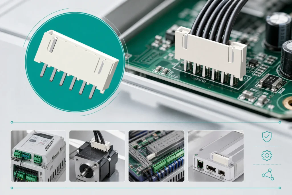
Why PCB Connectors Are Critical in Modern Electronics
When compared to passive components, circuit board connectors are typically subjected to the greatest amount of mechanical stress and are the most likely to fail in an electronic system. Connectors can also provide a physical connection between different electronic components (the connectors themselves are structural).
Common failure mechanisms include:
- Fretting corrosion under micro-vibration environments
- Contact resistance drift over long operational cycles
- Thermal expansion mismatch between mating components
- Insertion wear from repeated assembly cycles
For highly reliable systems such as Automotive ECUs and Industrial controllers, even a slight degradation in performance as a result of PCB connections can result in instability in the system.
Definition: Contact resistance drift indicates the slow increase in electrical resistance found at a connector interface due to factors such as wear, oxidation, or microscopic changes to the surface over time.
PCB Connector Types Classification Based on Engineering Function
| Category | Typical Products | Function | Engineering Focus |
|---|---|---|---|
| Signal Integrity Connectors | PCB pin connectors, board mount headers | High-speed data transmission | Low loss, impedance control |
| Power Connectors | PCB power connector | Current delivery | Thermal stability, low resistance |
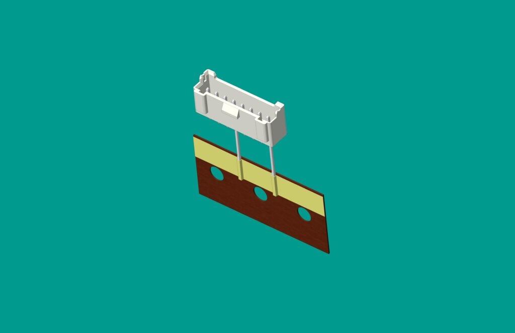
| Board-to-Board Connectors | board to board connector | Multi-PCB interconnection | Alignment precision |
| Wire-to-Board Connectors | PCB wire connector, pcb connector plugs | External wiring interface | Mechanical retention |
| Hybrid Interconnect Systems | printed circuit board connectors | Multi-function integration | Signal + power + structure |
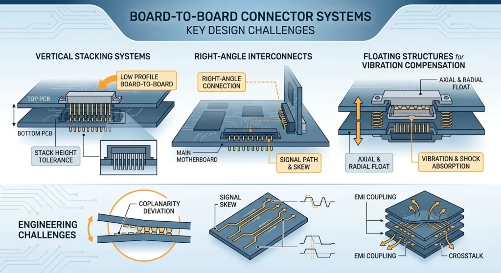
Board-to-Board Connector Systems and Design Challenges
board to board connector Compact electronic assemblies often have interconnections between multiple PCB layers using system types of wiring.
- Vertical stacking systems
- Right-angle interconnects
- Floating structures for vibration compensation
Modern electronics increasingly adopt low profile board to board connector designs.
Key engineering considerations:
- Stack height tolerance accumulation
- Coplanarity deviation between boards
- Signal skew in high-speed differential pairs
- EMI coupling in dense multilayer layouts
Signal skew: “Signal skew” designates the difference in arrival time for signals transmitted over parallel paths in a high-speed PCB system.
PCB Connector Manufacturing Process and Quality Control
The performance of pcb connectors depends heavily on manufacturing precision and process control.
Material Engineering
- Copper alloy contacts
- LCP housings
- Selective gold plating
Manufacturing Process
- Progressive stamping
- Electroplating (gold/tin/nickel)
- Injection molding
- Automated assembly alignment
| Failure Mode | Root Cause | Impact |
|---|---|---|
| Contact Resistance Drift | Wear / oxidation | Signal instability |
| Fretting Corrosion | Vibration + humidity | Intermittent failure |
| Thermal Fatigue | Thermal cycling | Structural cracking |
| Insertion Wear | Repeated mating | Reduced retention |
Definition: Statistical Process Control (SPC) utilizes statistical techniques as a quality-control method to track production variation.
Environmental Reliability and Real-World Conditions
printed circuit board connectors operate under harsh environments such as humidity, vibration, and thermal cycling.
- Humidity-induced oxidation
- Thermal cycling (-40°C to +125°C)
- Mechanical vibration
- Dust contamination
Engineering-Based Selection Guide
Choosing the appropriate PCB connector type entails a methodical analysis of electrical, mechanical and environmental aspects. Poor choice of connector can cause issues with signal quality, overheating or long-term reliability of PCB connection system.
Current Rating and Thermal Derating
The PCB power connector’s present rating specifies the highest allowable electrical load at a time when the connector is under normal operating conditions. In practical uses, however, both temperature rise and environmental conditions will result in thermal derating of the power connector rating.
Key considerations:
-
Operating current vs. peak current difference
-
Temperature rise under continuous load
-
Contact resistance influence on heat generation
-
PCB copper trace contribution to thermal behavior
If a high power application doesn’t derate properly enough, it can cause connectors to overheat, fail prematurely, and/or accelerate the aging of the pcbs that will be used with these connectors for an extended time period.
Signal Speed and Impedance Matching
In high-speed digital designs, connectors on circuit boards should have controlled impedance and very low signal distortion.
Key design factors:
-
Impedance consistency across contact pairs
-
Minimization of insertion loss and reflection
-
Reduction of crosstalk between adjacent pins
-
Stability in differential pair transmission
Data loss, jitter and timing errors may occur when using connector systems where the board to board connectors do not have appropriate impedances.
PCB Layout Constraints
Mechanical and spatial limitations of the PCB directly influence connector selection.
Key constraints include:
-
Available board edge space for connector placement
-
Vertical height limitation for low profile board to board connector designs
-
Routing space for high-density pin assignments
-
Clearance requirements for assembly and maintenance
To prevent assembly or performance issues, designers have to coordinate electrical traces and mechanical encloser constraints for connector placement on print circuit boards.
Mating Cycle Life
Insertion and removal cycles are referred to as mating cycles, and ‘mating cycle life’ measures how many times a connector can be properly inserted and removed from a PCB with minimum performance degradation.
Key considerations:
-
Contact material wear resistance
-
Spring force retention over time
-
Surface plating durability (gold or alloy coatings)
-
Application usage frequency (maintenance vs. fixed installation)
For high-cycle pcb pin connector requirements found in industrial and automotive applications, durability is key; for consumer products, mechanical robustness may be less important than packaging size.
Industry Applications
Automotive Electronics
Automotive PCB connectors are widely used as part of a wide variety of ECUs, BMSs (battery management systems), power control modules, etc. The connectors must endure vibration and thermal cycling while providing long-term reliability.
Industrial Automation
Industrial Automation Equipment Uses Sharp Board Connectors To Provide A Reliable Signal Transfer And Power Supply Of P.L.C. Controllers, Motor Power Control Equipment And Industrial Control Panels And Other Types Of Equipment In A Harsh Environmental Setting.
Telecommunications
Telecom infrastructure utilizes High-Speed PCB Connectors in base stations, servers and other networking devices to facilitate high-speed data transmission at high frequencies with low signal attenuation.
Medical Devices
To maintain the consistent functioning of diagnostic systems, monitoring devices and other life-sustaining equipment, medical devices rely on highly dependable printed circuit board connectors.
Consumer Electronics
In order to promote both miniaturization and high density integration in consumer electronic devices like laptops, smartphones and wearable devices, there are many electronic designs that use PCB wire connectors and compact board-to-board connectors (BBBCs) for interconnecting the components of an electronic system.
Case Study: High-Reliability PCB Connector Selection in Automotive ECU Systems
A Tier-One Car Producer created an Electrical Control Unit System (ECU) that would withstand harsh environmental conditions such as extreme vibration and temperature changes.
The initial design used a standard board to board connector solution.
Engineering Issues
- Signal instability after thermal cycles
- Contact resistance increase
- Micro-displacement under vibration
Optimization
- Upgraded to low profile board to board connector
- Improved LCP housing stability
- Optimized stack height
- Improved plating thickness
Results
- Thermal cycles improved from 200 → 1000+
- Reduced resistance variation by 35%
- No signal interruption under vibration tests
OEM/ODM Engineering Collaboration
Quality Assurance Beyond Certification
- SPC monitoring
- Burn-in testing
- Lifecycle simulation
- Traceability systems
FAQs
What are the main types of PCB connectors?
Signal, power, board-to-board, and wire-to-board connectors.
How do I choose a board-to-board connector?
Consider pitch, stack height, and electrical requirements.
What causes PCB connector failure?
Vibration, corrosion, thermal cycling, and wear.
Can PCB connectors be customized?
Yes, OEM customization is supported.
Which industries use PCB connectors?
Automotive, industrial, telecom, medical, consumer electronics.


