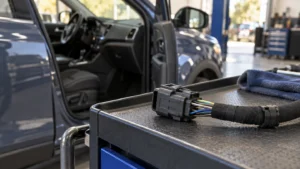
Comprehensive Guide to PCB Board Connector Types
A connector list can become confusing when it mixes wire-to-board, coaxial, circular and SMT as though they were competing choices. They describe different things: what connects, what the circuit carries, how the housing is shaped and how the component is attached. A single part can belong to several of those categories at once. This guide keeps the useful families from the original comparison but separates those classification axes, so an engineer can shortlist a connector without overlooking board orientation, a flex-cable interface or the production process. That distinction also makes a supplier quotation easier to compare.
The short answer is to classify PCB board connector types by the interface first: wire-to-board, board-to-board or an external I/O connection. Then add the circuit requirements, such as RF, high-speed data or power, and select a compatible mounting method. TE Connectivity’s PCB connector overview describes multiple product families rather than one universal board interface. The shortlist should identify both mating parts and their drawing revisions. A shared pitch or contact count is not enough to decide that two families can replace each other.
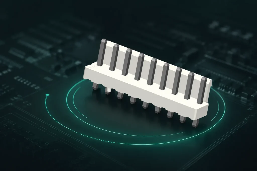
PCB connectors make electrical interfaces separable. The type comparison below starts with the parts being connected and then adds the service and assembly requirements.
Why does the PCB interface matter to assembly and service?
Connectors on printed circuit boards give electronics the ability to function properly as they provide connections between different parts of various electronic systems without having to solder wires directly onto the circuit board. Connectors allow for increased flexibility in terms of assembly, ease-of-maintenance, and scalability of the system, making them ideal for creating durable designs with maximum adaptability to different operating requirements.
Which PCB connector families should be compared?
Various types of connectors have been developed for specific requirements; thus, different types of connectors have different features and advantages unique to each type of connector. This article describes some of the most common types of PCB connectors:
When is a wire-to-board connector needed?
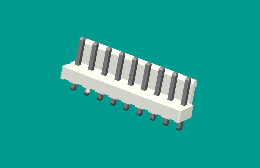
Individual wires/cables can be connected to PCBs easily through the use of Wire-to-Board connectors. When using Wire-to-Board connectors in your application, you will often find they are designed to fit into tighter spaces than standard connectors and provide a secure and durable connection. Examples include:
- Pin Headers
- Terminal Blocks
- IDC Connectors (Insulation-Displacement Connectors)
When should two boards be connected directly?
Board-to-board connectors function as a bridge, connecting different PCBs together electrically even though those boards may be modules themselves. Compact electronic systems (e.g., consumer electronics/industrial equipment) require board-to-board connectors to preserve valuable internal space and maintain high levels of electrical signal repeatability.
| Type |
Key Features |
| Stacking Connectors |
Align PCBs and support multi-layer structures. |
| Mezzanine Connectors |
Highly compact and support high-density connections. |
| Edge Connectors |
Offer direct connection using PCB edge. |
What makes a coaxial interface different?
In RF applications, coaxial connectors are utilized for sending RF (radio frequency) signals such as for use with antennas and communication devices. They are shielded to help prevent loss of signal and to reduce interference.
Which connectors provide external I/O ports?
Connection points on input/output (I/O) ports connect to other devices or peripherals connected via printed circuit boards (PCBs). These types of connectors exist in most consumer electronics, computers, or industrial products. However, here are some examples:
- USB Connectors
- HDMI Connectors
- VGA Connectors
When does a circular housing suit the board interface?
A circular housing may be part of a board-mounted external interface. Its shape does not define the circuit function, sealing or vibration capability. Check the selected mating pair, panel or board mounting and the required environmental evidence.
What must a high-speed connector support?
As the popularity of data-heavy applications increases, fast data transfer with minimum interference is possible through high speed connectors, thus making these connectors an excellent fit for industries such as telecommunications and networking.
Which specifications determine whether a PCB connector fits?
When selecting a PCB connector, pay careful attention to the following specifications:
| Specification |
Why It Matters |
| Current Rating |
Compare the rated configuration and temperature limits with the actual circuit load. |
| Voltage Rating |
Check the rated voltage and applicable insulation requirements for the installation. |
| Insertion Force |
Impacts ease of assembly and disassembly. |
| Pin Count |
Defines the number of possible electrical connections. |
| Material |
Compare the specified housing, contact material and finish with the intended exposure. |
Which design changes require a fresh connector review?
A smaller enclosure, a different cable exit, a higher data rate or a revised current load can change the suitable connector even when the circuit count stays the same. Recheck the complete interface after such changes instead of carrying forward the previous family rating.
- For a smaller board, compare mating access and retention features as well as pitch.
- For a higher data rate, verify the connector, launch, routing and cable as a channel; a USB-C shell does not by itself specify supported speed.
- For a modular assembly, confirm the expected service operation and connector cycle limit.
- For a changed material or finish, request the revised specification and relevant evidence rather than assuming the same durability.
When are two PCB connectors not interchangeable?
Two parts can share a pitch or pin count and still fail to mate or perform safely. Check the housing and contact geometry, gender, keying, contact length, plating, board footprint, mounting orientation, retention and the approved mating part. Also compare the electrical and environmental ratings under the same loading and test conditions.
For procurement, keep the connector drawing, mating-part number, PCB land pattern and assembly instruction together. This prevents a visually similar replacement from entering production without evidence of mechanical, electrical and process compatibility.
Why should interface type, circuit function and mounting be kept separate?
| Classification question |
Examples |
What it does not decide |
| What is connected? |
Wire-to-board, board-to-board, external I/O |
Current, data performance or solder process |
| What does the circuit carry? |
Power, RF, high-speed data, control signals |
The physical board arrangement |
| How is it attached to the PCB? |
SMT, through-hole, press-fit where specified |
The approved mating part |
| What is the housing format? |
Rectangular, circular, open header |
Sealing or electrical capability without a product specification |
JLCPCB’s PCB connector guide includes SMT, through-hole and press-fit approaches. Press-fit is a distinct option, not a form of soldered through-hole assembly. Where it is selected, obtain the supplier’s finished-hole and insertion-process requirements; do not substitute a conventional plated-hole pattern without checking them.
How does board orientation change a board-to-board connector choice?
Record the mechanical arrangement before choosing the pitch. Harwin distinguishes parallel or mezzanine, right-angle and coplanar board arrangements. A board-to-board label does not specify the resulting stack height or clearance.
| Board arrangement |
First mechanical check |
Assembly question |
| Parallel boards |
Mated stack height and component clearance |
Can both boards be aligned and supported without loading the contacts? |
| Right-angle boards |
Board edge, mating axis and enclosure clearance |
Is the required insertion motion accessible? |
| Coplanar boards |
Edge-to-edge position and alignment |
Which features control the relative board position? |
What must match when selecting an FFC or FPC connector?
FFC refers to a flat flexible cable and FPC to a flexible printed circuit. These names do not establish one interchangeable termination. Match pitch, circuit count, contact side, flex thickness, exposed-contact length and retention features to the connector drawing. Check whether the latch opens by lifting or sliding and whether the cable needs a stiffener. A same-pitch flex that is too thick or presents its contacts on the wrong side is not an acceptable substitute.
For a high-speed interface, keep the channel evidence separate from physical fit. IEC 60512-1:2018 provides a connector-test framework, but the detail specification selects the tests and limits. A general test-method reference does not replace configuration-specific signal-integrity data.
Frequently asked questions
What are the main types of PCB connectors?
Start with wire-to-board, board-to-board and external I/O interfaces. Headers, sockets, flex-cable connectors and card-edge receptacles are physical implementations; RF, power and high-speed labels describe circuit service. Keeping these axes separate avoids comparing unlike choices.
How can two PCBs be connected together?
Use a mating board-to-board pair, a card-edge interface or a cable between board-mounted connectors, depending on the board arrangement and service needs. Define orientation, separation, alignment and support before selecting pitch or pin count.
What is the difference between FFC and FPC connectors?
FFC and FPC describe the flexible cable or circuit being terminated. A connector may support one or both only within its specified dimensions. Check pitch, contact side, thickness, contact length, stiffener and latch details rather than assuming compatibility from the name.
Is a card-edge connector the same as a pin header?
No. A card-edge interface uses plated contacts on the PCB edge, while a pin header uses projecting contacts in a separate component. Board thickness, edge geometry, plating and insertion depth therefore become important card-edge mating requirements.
Are SMT, through-hole and press-fit interchangeable mounting choices?
No. Each needs the corresponding connector variant, board pattern and assembly process. SMT and soldered through-hole use soldered terminations; press-fit relies on a specified contact-to-hole interface. Do not reuse a footprint or process without checking the manufacturer's requirements.
Does UL or ISO certification prove that a PCB connector is suitable?
Not by itself. Verify the exact product or organization covered, the applicable standard, edition and scope. A management-system certificate is not a connector mating specification, and a component approval does not establish that the finished equipment meets its requirements.
Conclusion
The useful comparison between PCB connector types begins with the interface, not with the longest catalogue list. Decide whether the product connects a harness, another board or an external device, then define the circuit service and mounting process. Board orientation and flex-cable geometry deserve their own checks because they can rule out a part before electrical ratings are compared. Do not treat a matching pitch, an identical-looking housing or a general certification as permission to substitute a different family. Keep the mating drawing, board pattern and required performance evidence together. ZUCH’s connector options can help with the initial shortlist; final selection should follow the exact interface and application requirements.
 Zhejiang ZUCH Technology Co., Ltd.