Circular Connector Guide for Electronics Engineers
Two round connectors can look alike and still have incompatible keys, contact arrangements or wiring. Choosing by diameter and pin count is especially risky when a machine uses several sensor, network and power ports close together. An IP marking adds another question: which assembled state was actually tested? This guide explains the circular connector choices that affect an electronics design, including locking, termination, coding and cable space. It also shows how to compare a connector with a rectangular or board-level alternative without assuming that a circular housing is automatically stronger, better sealed or electrically suitable.
The short answer is to select the complete circular interface: shell and coupling, coding, contacts, termination, cable entry and the required sealing arrangement. For an M12 connection, the coding letter and pinout matter as much as the thread. For another family, use its specific interface drawing. The Amphenol LTW M12 coding guide, published 20 September 2026, explicitly separates coding from contact count, wiring and part-specific ratings. Check the intended application and assembly before assuming that two connectors with similar housings can be substituted.
Which standards and market requirements apply to a circular connector?
Standards and market requirements answer different questions. A dimensional or interface standard can define geometry, contact arrangement or test methods; a product certification or declaration addresses a particular market or end-product requirement. RoHS and REACH concern substances and chemical compliance, CE is a market-conformity framework, and an IP code describes an ingress test scope. None of these labels alone proves that a circular connector will mate, carry the required load or survive the installation.
Ask the supplier for the controlled drawing, mating interface, electrical ratings, application specification and configuration-specific test reports. The applicable standard edition and certification scope should be recorded in the project file rather than inferred from a logo or product photograph.
Which locking method suits the vibration and service conditions?
The locking technique determines how tightly the circular connector remains in place while vibrating, moving around or operating regularly. Some typical circular connector locking methods include thread locking, bayonet locking, push-pull locking and snap-in locking.
A threaded, bayonet or push-pull interface changes the assembly motion and service access. Select the mechanism from the documented vibration capability, installation space, required tool or hand access and expected service frequency. Threading does not prove vibration performance by itself, and push-pull is not automatically the best choice for every small device. Check full engagement and the supplier’s coupling instructions for the selected design.
Which termination method suits the harness and assembly process?
Various procedures are involved in connecting the electrical wires to the contacts of a circular connector. Some examples of such processes are solder terminal, crimp terminal, screw terminal, and complete circular connector assembly.
Solder, crimp and screw terminations require different preparation, tooling and inspection. A controlled crimp can provide a repeatable harness connection, while other methods may suit a different production or field-service process. None is universally superior in vibration. A preassembled cordset can reduce on-site wiring steps, but its circuit mapping, cable and sealing conditions still need verification.
|
Termination Method
|
Best For
|
| Solder termination |
Factory assembly |
| Crimp termination |
Harness assembly with controlled crimp tooling and inspection |
| Screw terminal |
Field installation |
| Cable assembly |
OEM connector solutions |
The choice of termination method needs to be made depending on factors such as the volume of production, the size of the cables, and the conditions of the work environment.
What is the difference between IP67 and IP68?
The IP code uses one digit for protection against solids and a second digit for water exposure. Under IEC 60529, IP67 indicates dust protection plus temporary immersion under the defined test conditions. IP68 indicates dust protection plus immersion under conditions specified for the product, such as depth and duration; those conditions must be stated by the supplier or test authority.
Neither label alone proves resistance to pressure washing, chemicals, vibration or continuous service. Review the complete mated connector, cable entry, backshell, unused cavities, mounting orientation and sealing accessories, and validate the assembly in the actual installation before production.
Which circular connector family suits the circuit and environment?
All circular connectors are of various types designed depending on various electrical and mechanical specifications. Different types of circular connectors are Power connectors, signal connectors, data connectors, waterproof connectors, military, aviation, and hybrid connectors.
|
Connector Type
|
Common Use
|
| Circular power connector |
Power supply and equipment wiring |
| Signal connector |
Sensors and control systems |
| Data connector |
Communication and data transfer |
| Waterproof connector |
Outdoor and wet environments |
| Hybrid connector |
Power, signal, and data in one unit |
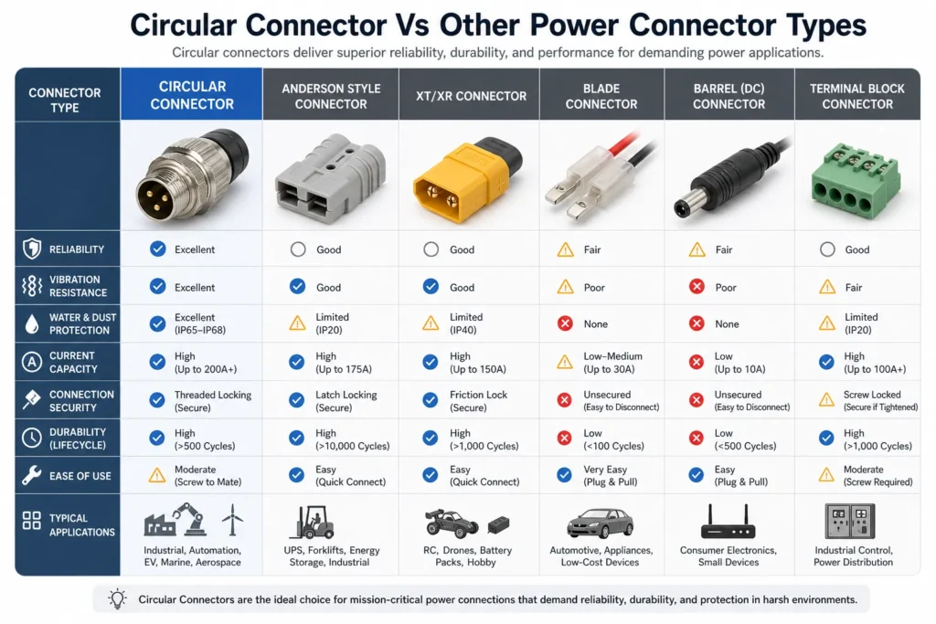
When is a circular connector preferable to a rectangular connector?
A circular connector can be useful where the selected coupling, panel mounting and cable-entry arrangement fit the installation. A rectangular connector may package a different contact arrangement more effectively. Compare the exact products for retention, sealing, loading and access; the housing shape alone establishes none of those performance results.
|
Connector Option
|
Main Advantage
|
Best For
|
| Circular connector |
Defined circular coupling and cable-entry arrangement |
Industrial equipment |
| Rectangular connector |
High contact density |
Control cabinets |
| Terminal block |
Easy field wiring |
Maintenance wiring |
| Board-to-board connector |
Compact PCB connection |
Internal electronics |
| Simple power plug |
A simple separable interface where its ratings and retention suffice |
Basic power devices |
Both circular and rectangular designs can provide sealing when their specified mating and installation conditions are met. Compare the actual test scope rather than treating round geometry as proof of better ingress protection.
That being said, there are instances where circular connectors should not be chosen. There are cases where the use of rectangular connectors is more suitable especially when a good number of contacts are required in a way that they will fit into a flat space. Board to board connectors may also come in handy if you need to make compact PCB level connections. In some cases, terminal blocks may also be most ideal in situations that require field wiring and maintenance as compared to other connectors.
The critical question for electronics engineers is not whether circular connectors outperform different electrical power types.
The fact is whether they meet the requirements for the current rating of the application and various other aspects, such as installation environments and maintenance needs.
How should shell size, contacts and keying be specified?
Shell size, contact arrangement and coding jointly define the available interface. Do not infer current capacity from outside diameter or circuit function from pin count. Circular power connectors are not restricted to two or three contacts, and a signal connector does not necessarily need more than three. Select the documented contact layout and ratings for the actual circuit assignment.
In the pin selection process, engineers have to think about the total number of the lines used for power transmission, signal transmission, grounding, shielding, and expansion needs. For instance, a motor control system might need different connections for robot motor power transmission, signal transmission from sensor parts, and signal communication lines.
The way the pins are spaced is also essential. In high voltage applications, there usually needs to be enough space between the contacts and creepage distance. In high current applications, the contacts need to be made of the right materials and coating process so the power dissipation is lowered.
To ensure that any standard circular connector is developed in accordance with the specifications, it is essential for engineers to refer to the data sheet, which must contain all necessary information including but not limited to rated voltage/current per contact, insulation resistance, contact resistance, wire gauge range, panel cut-out size, and mating cycle life.
Pin Configuration:The number, layout, and function assignment of pins inside a connector.
What does a robotics application need from a circular connector?
Robotics and automation connections may face repeated motion, vibration and mixed power or data requirements. Circular connector families can suit these installations, but their electrical and mechanical capability must be checked for the selected cable assembly.
Robots utilize circular connectors for many purposes: they can operate servos, other types of motors, sensors, encoders, motion controllers or any other devices related to power distribution. For instance, a round electrical connector may supply power to a servo motor.
When it comes to automation equipment, circular electric connectors are one of the most used industrial types of connectors. In factories, circular electric connectors are found to be used in a wide range of applications such as factory machinery.
Engineers have to be mindful of the proofing against vibrations, flexibility of the cable, effectiveness of shielding, number of mating cycles possible, and IP rating of the connectors selected for use in robotics and automation. It is just as important to consider the cable design itself, including strain relief, as it is the circular connectors themselves.
Mating-cycle life is the specified number of connection and disconnection cycles under defined conditions. It is not the operating frequency of the equipment.
In the case of fast data transfer signals, engineers should also consider the requirements regarding shielding and impedance control and protecting against those unwanted electromagnetic interferers. Evaluate the connector and cable together; any reliability or maintenance-cost comparison should use the documented configuration and a defined service procedure.
Which checks prevent a circular connector mismatch?
It is common to make the mistake of selecting a circular connector merely by its appearance or the number of pins. Even if two connectors look the same, there are many differences that can be identified, such as their current rating, voltage rating, waterproof level, material quality, and how the connector locks.
Furthermore, there is a common error of overlooking the real working conditions of the connector. It is true that a connector utilized indoors can possibly operate with lower IP rating. However, in the case of using a connector used outdoors, near water sources, or in an industrial environment where dust is present, a connector needs to be waterproof.
Engineers should also avoid underestimating current load. If the selected circular power connector cannot handle the required current, the contacts may overheat during operation. This can reduce connector life and create safety risks.
A third mistake is overlooking cable compatibility. The connector should match the cable diameter, wire gauge, shielding structure, and installation method. Even a high-quality connector may fail if the cable is not properly fixed or sealed.
Compare installed cost, including the mate, accessories, assembly, inspection and replacement access. A lower unit price does not prove a higher failure rate, and a higher price does not prove reliability. Use the required qualification evidence and service task to compare alternatives.
What should a circular connector RFQ include?
When buying circular connectors for electronics projects, engineers should start by defining the application requirements. These include current rating, voltage rating, number of pins, signal type, cable size, working temperature, protection level, installation method, and expected service life.For power applications, choose a circular power connector with enough current capacity and reliable contact design. For signal applications, focus on contact stability, shielding, and pin density. For outdoor or industrial applications, choose waterproof circular connectors with suitable IP ratings and durable housing materials.Engineers should also decide whether they need a standard circular connector or a customized solution. Standard connectors are easier to source, replace, and maintain. Custom connectors may be useful when the project has special requirements for pin layout, cable assembly, branding, color, or mounting structure.Before placing an order, it is useful to request samples and test them under real operating conditions. Engineers should check the mating force, locking reliability, cable fit, sealing performance, and electrical stability. For production projects, suppliers should also provide consistent quality, clear technical drawings, and stable delivery capability.

What must be checked when the connector is unplugged?
An ingress rating for a mated assembly may not apply to an exposed port. Confirm whether unmated protection requires a specified cap, which sealing accessories are needed and how the service procedure protects the interface. IEC 60529 classifies enclosure protection; it does not establish cable-flex life, chemical resistance, current capacity or a safe live-disconnect procedure.
Why are M12 coding and pin count separate compatibility checks?
M12 identifies the metric interface format, not a universal pin assignment. Coding changes mechanical keying and corresponds to defined applications, while contact count and wiring still need to match the device. NorComp’s coding explanation and the Amphenol LTW guide distinguish A-coded sensor/I/O uses from D- and X-coded Ethernet uses. A four-contact sensor cordset cannot be substituted for an Ethernet cordset just because the contact count is the same.
| Selection check |
What to compare |
What remains separate |
| Coding |
Letter code and physical keying of both halves |
Pin functions and part-specific ratings |
| Contact arrangement |
Contact count, gender and numbered positions |
Device protocol and cable mapping |
| Cordset |
Pin-to-pin or adapter wiring, cable construction and shield path |
Channel performance and installation conditions |
| Sealing state |
Mated assembly or documented unmated protection |
Chemical exposure, flexing and electrical duty |
How can a mirrored pinout mistake be avoided?
Record whether the drawing shows the mating face or the termination side, and whether it depicts pin or socket contacts. Do not copy the spatial arrangement from one view into the opposite view. Use the manufacturer’s numbered drawing and cordset mapping, then check the required continuity before release. Wire colour is not a universal substitute for pin identification; Amphenol LTW specifically warns that colours can vary by cordset and manufacturer.
How much space should be reserved behind a circular connector?
Use more than the connector-body length when checking the enclosure. Include coupling travel, hand or tool access, backshell length, cable exit direction and the cable’s specified bend space. A right-angle exit can alter the direction of the required clearance without eliminating it. Check the connector and cable inside the installed enclosure, including the route used to unplug or replace the assembly.
When a panel interface is not needed, a board-to-board or wire-to-board connection may be a better starting point. For maintenance wiring, compare fixed and pluggable connections against the same service task. These are application decisions, not claims that one form factor is always superior.
IEC 60512-1:2018 links connector tests to detail specifications and prescribed limits. Request that configuration-specific evidence rather than accepting a general vibration or “industrial-grade” label.
Frequently asked questions
Are circular connectors interchangeable when the diameter and pin count match?
No. Compare coding, contact arrangement, gender, coupling, the approved mating interface, termination, sealing and ratings. Similar outside dimensions or a shared M12 label do not confirm the device pinout or cable mapping.
Can a four-pin A-coded M12 connector replace a four-pin D-coded connector?
Not on contact count alone. The coding and intended wiring differ. A-coded interfaces are commonly used for sensors and I/O, while D-coded interfaces are commonly used for industrial Ethernet. Match the device port, coding and documented cordset mapping.
Does IP68 mean a circular connector is suitable for every wet environment?
No. Confirm the product's immersion conditions and the exact assembly covered. Do not infer pressure-washing, chemical or cable-flex capability from IP68. Verify whether the stated protection is mated only or needs an accessory in the unmated state.
How can the correct pinout be read from a connector drawing?
Identify the viewing direction and whether the drawing shows the pin or socket interface. Use its pin numbers and the device or cordset mapping, not a mirrored visual guess or wire colour alone. Check the required continuity before the assembly is released.
Is a threaded circular connector always better than a push-pull design in vibration?
No. Compare the documented performance of the selected designs under the required conditions. Coupling instructions, full engagement, cable loading, support and service access matter. A locking-method name is not evidence of the assembled vibration result.
Can a circular power connector be disconnected while energized?
Do not assume that it can. Mechanical separability does not establish switching or load-breaking capability. Follow the equipment isolation procedure unless the exact connector and application are explicitly documented for the intended energized operation.
Conclusion
A circular connector is a useful choice when its complete interface fits the equipment, not simply because its housing is round. Start with the device function and electrical duty, then match coding, contacts, pinout and the approved mating pair. Check coupling access, cable exit and sealing in the installed assembly, including what happens when the connector is unplugged. Do not treat an IP label as evidence for vibration, chemicals or energized disconnection, and do not infer current capacity from shell size. Where a board-level or maintenance-wiring interface fits better, compare that alternative against the same requirements. ZUCH’s product documentation should be assessed at the exact-part level before a component is accepted into an equipment design.
 Zhejiang ZUCH Technology Co., Ltd.