Zhejiang ZUCH Technology Co., Ltd.
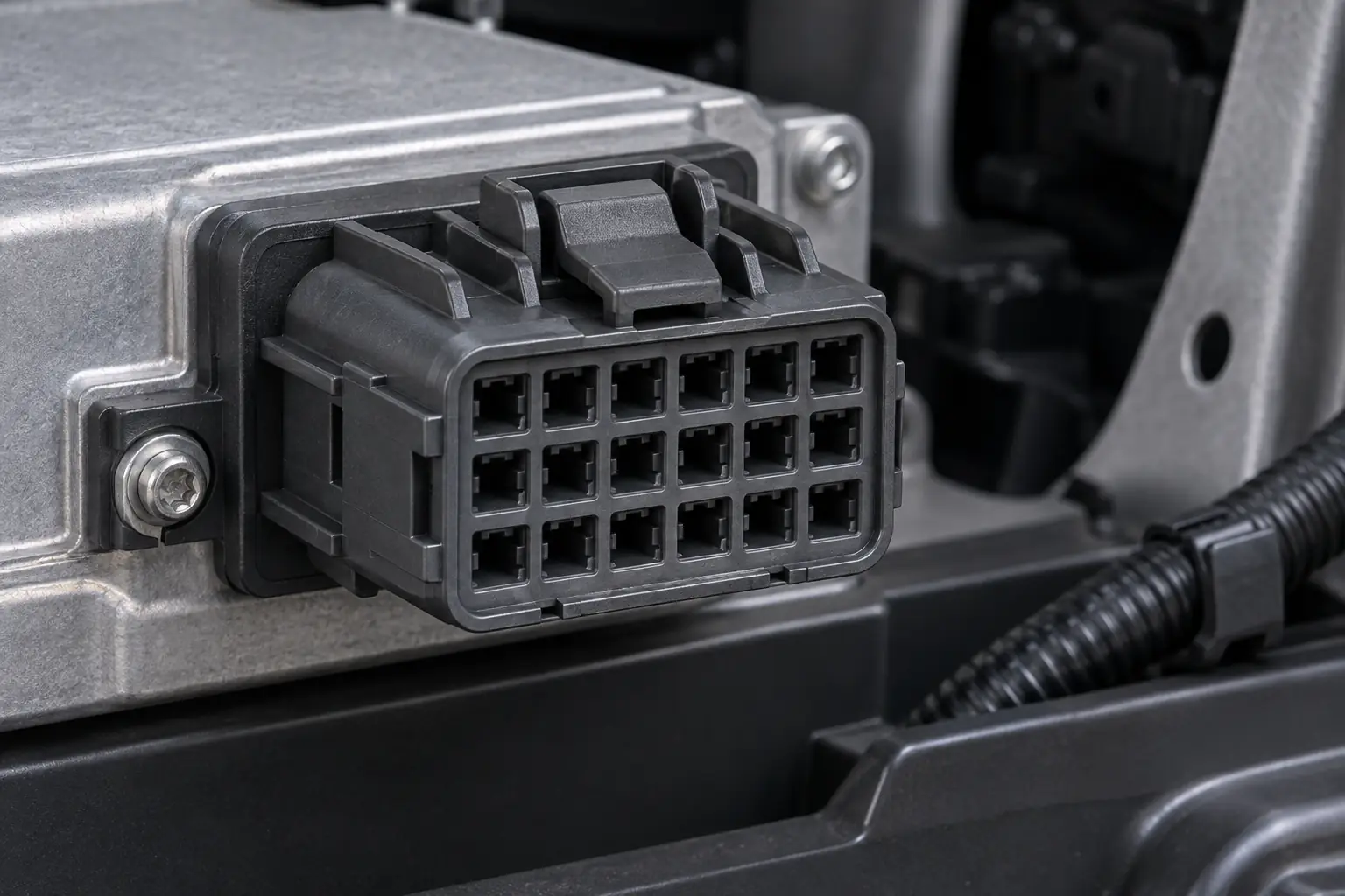
When a harness engineer in Stuttgart encountered a module that would not wake during a prototype build, the engineer fitted an 18-position connector that looked compatible. The first powered check failed immediately. The connector was not defective: the team had compared a harness-side cavity view with a mirrored mating-side view and had not verified the key code.
Summary: Select an 18 pin automotive connector as a complete, documented interface—not by pin count or appearance. Eighteen cavities do not guarantee the same layout, keying, terminal system or circuit assignment. Confirm the viewing direction, mating housings, cavity map, terminals, wire and seal ranges, then test retention and continuity on a representative harness. SAE/USCAR-2 and ISO 8092-2 provide useful automotive performance frameworks; neither makes an unverified part universally interchangeable.
An 18-position interface can consolidate power, ground, sensor, actuator and communication circuits, but it may also contain unused cavities. The real question is whether the complete interface matches the intended system.
An 18-Circuit Interface Makes Sense Only When the System Needs It
Eighteen circuits can suit body controllers, seat or door modules, lighting assemblies and HVAC controls. The number 18 describes positions, not current capacity. Assign each populated circuit individually and manage unused cavities according to the connector design.
Consolidation can reduce mating operations, but it concentrates consequences: one poorly seated contact can disable one function, while housing damage can affect all 18 positions. ISO 8092-2 frames general performance requirements and test methods in its defined scope; the vehicle maker’s validation plan remains controlling.
Total cost includes both housings, terminals, seals, plugs, tooling, inspection and service stock. A lower housing price is not a saving if it creates rework or another validation cycle.
How Do Viewing Direction, Cavity Layout and Keying Prevent a False Match?
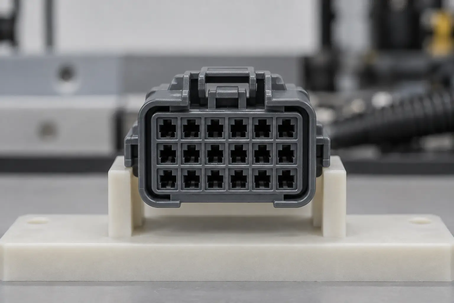
Start with a drawing showing cavity numbers, row and column arrangement, latch and viewing direction. A front-face view is mirrored relative to the wire-entry view of its mate; copying an 18-cavity map without that reference can transpose every circuit.
Key ribs, polarization features and latch geometry work only when both sides use the intended family and key code. Two 18-position housings may reject each other—or appear to mate while contacts do not engage correctly. SAE/USCAR-2 treats performance as a system attribute, so a hand-fit is not sufficient evidence.
For an 18 pin automotive connector, the release package should include housing part numbers, approved mate, cavity map, terminal orientation and secondary-lock position. Verify full latch engagement without excessive force; forcing a mismatched key can damage the guides.
How Can You Prove That Two 18-Position Connectors Are Interchangeable?
Eighteen positions alone do not prove interchangeability. Start with the manufacturer family and complete part numbers, including suffixes that identify key code, color, seal option or material where applicable. Confirm whether each part is a harness housing or device header, and obtain the controlled drawings for the stated revisions rather than treating a marketplace description as fit evidence.
Orient both drawings from the connector face with the latch in the same reference position. Compare keying and polarization, latch geometry, cavity pitch, row arrangement and cavity numbering. Then verify the terminal system and contact size: housings with a similar outline or identical cavity count can use different receptacles, tabs or hybrid contact sizes and may not provide the required terminal engagement.
- Retention: Match the CPA, TPA or other secondary-lock part, its pre-lock and final-lock positions, and its relationship to the terminal retention features.
- Seal package: Compare the interface seal, individual wire seals, cavity plugs and permitted insulation diameters; a sealed housing is not equivalent if its seal package does not match the wires.
- Wire range: Check conductor area, insulation diameter, crimp specification and the electrical and temperature requirements for every populated circuit.
- Mating definition: Compare the exact housing-to-housing or housing-to-header drawing, including datum dimensions, polarization features and specified terminal engagement.
Use a conservative decision rule: treat the parts as non-interchangeable until every item is documented as a match. Next, inspect a representative mated pair, confirm that the latch and CPA/TPA reach their final positions, and perform the required retention, continuity, isolation and application validation. An adapter or repin may resolve a mismatch, but it creates a new assembly configuration that needs its own drawing, process controls and approval.
Why Must Terminals, Wire Range, Secondary Locks and Seals Be Specified Together?
The terminal must match the cavity, mating contact and conductor. Specify conductor cross-section, insulation diameter, plating, current, temperature and tooling. Wire gauge alone is incomplete because equal conductor areas can have different insulation diameters and require different seals.
Primary retention usually comes from a terminal lance or housing feature; a secondary lock adds another control. Verify all 18 populated positions visually and with the defined retention check. SAE/USCAR-2 includes mechanical test concepts, but force limits must come from the drawing and customer specification.
Crimp control should use the terminal maker’s strip length, crimp-height and pull-force criteria. In sealed versions, match each seal to the insulation diameter and fit specified cavity plugs. Sealing cannot correct a cut seal or cocked terminal.
How Should You Match Housing Gender, Repair Terminals and Verify Circuits?
“Male” and “female” can describe the housing or metal contact, so use part numbers and drawings. Confirm the mate, terminal sex, contact size, key, latch and cable exit. A device header may form one side; an inline connection normally needs two compatible housings.
One terminal can often be replaced if the cavity, lock, seals and housing remain undamaged. De-energize the circuit, follow the OEM repair instruction, open the secondary lock and use the correct extraction tool. Replace a distorted contact; then confirm seating and retention after installing the new crimp.
Continuity testing should cover 100% of repaired or new circuits on a de-energized harness, plus isolation where required. A multimeter beep confirms a path; it does not prove correct cavity assignment or loaded performance. Record the pin map, then apply the approved resistance, voltage-drop or functional test. High-voltage and airbag circuits require dedicated OEM procedures.
In an illustrative 500-harness build, eight minutes of repinning per harness equals about 67 labor hours. At an illustrative US$45 loaded hourly rate, that is roughly US$3,000 before retest, disruption or material loss—strong justification for drawing review and a representative sample.
Which 18-Position Connection Architecture Best Fits the Application?
| Architecture | Performance and compatibility focus | Unit-cost tendency | Maintenance and TCO implication |
|---|---|---|---|
| Sealed 18-position system | Mated seal, individual wire seals, plugs, retention and routing must work together | Usually higher than unsealed | Can reduce contamination risk when exposure justifies the added parts and process controls |
| Unsealed 18-position system | Best for protected locations; keying, contact loading and strain relief still matter | Usually lower | Simpler assembly, but unsuitable exposure can increase diagnostics and returns |
| Two smaller connectors | Can separate power from sensitive signals or create service zones | More housings and mating actions | May localize faults, but increases assembly steps and cross-mating controls |
| Custom or modified interface | Application-specific geometry, materials, tooling and validation | Higher development tendency | Can solve packaging needs, but change control and spare-part support become critical |
Validation Priorities Change with the Installation Environment
| Application pattern | Circuit and interface checks | Terminal/sealing checks | Priority validation |
|---|---|---|---|
| Body or comfort module | Mixed power, ground and signals; freeze the cavity map and key code | Confirm each wire range and aggregate thermal loading | Continuity, isolation, retention, vibration and temperature cycling |
| Door or seat harness | Packaging, repeated movement and service access | Strain relief, bend control and terminal back-out prevention | Flexing environment, latch operation and intermittent-event monitoring |
| Exterior lighting or equipment | Splash zone, mounting orientation and cable exit | Interface seal, wire seals and plugs for unused cavities | Ingress exposure, thermal cycling, retention and loaded voltage drop |
| Protected cabin module | Keying, service cycles and signal integrity | Unsealed design may be suitable if the environment supports it | Mating durability, continuity and application-specific functional checks |
Which Standards Apply, and What Do They Actually Demonstrate?
- SAE/USCAR-2 is a performance specification for automotive electrical connector systems. It supports structured electrical, mechanical and environmental evaluation; citing it does not prove that a particular part, crimp or harness has passed an OEM programme.
- ISO 8092-2:2023 addresses definitions, test methods and general performance requirements for road-vehicle on-board wiring-harness connections within its voltage-class-A scope. Confirm the required part, edition and customer-specific limits.
- IEC 61984:2008 applies to connectors above 50 V and up to 1,000 V AC/DC, with rated currents up to 125 A per contact, where its stated conditions are met. It is not vehicle-specific and does not replace SAE/USCAR, ISO or OEM requirements for a typical low-voltage automotive interface.
These documents are standards and test frameworks, not universal product certificates. Applicability depends on destination market, vehicle programme, voltage, intended use and the claims made. Unsupported “certified,” “waterproof” or “universal fit” language can cause rejected approvals, warranty disputes and repeated testing.
Five Actions Reduce 18-Position Sourcing and Validation Risk
- Freeze the interface. Record both housing part numbers, key code, latch, viewing direction, cavity numbering and module-side header information. Use this guide to identify automotive electrical connectors systematically.
- Freeze the circuit map. Assign every power, ground, signal and unused cavity; require independent checking of both drawing views.
- Specify the termination. List terminal, seal, plug, wire and tooling references. Establish controlled work instructions for crimping automotive connectors.
- Approve a representative pair. Build with production-equivalent wire, terminals, seals and tools, then verify mating, retention, continuity and the application test plan.
- Control commercial evidence. Request drawings, revision status, test scope, change notification and traceability appropriate to the programme.
ZUCH is a China-based connector-system manufacturer. When discussing an 18 pin automotive connector, provide the cavity map, mating details, wire dimensions, environment and required evidence so selection starts from the application.
Frequently Asked Questions
What is an 18-pin automotive connector typically used for in expanded harness and module connections?
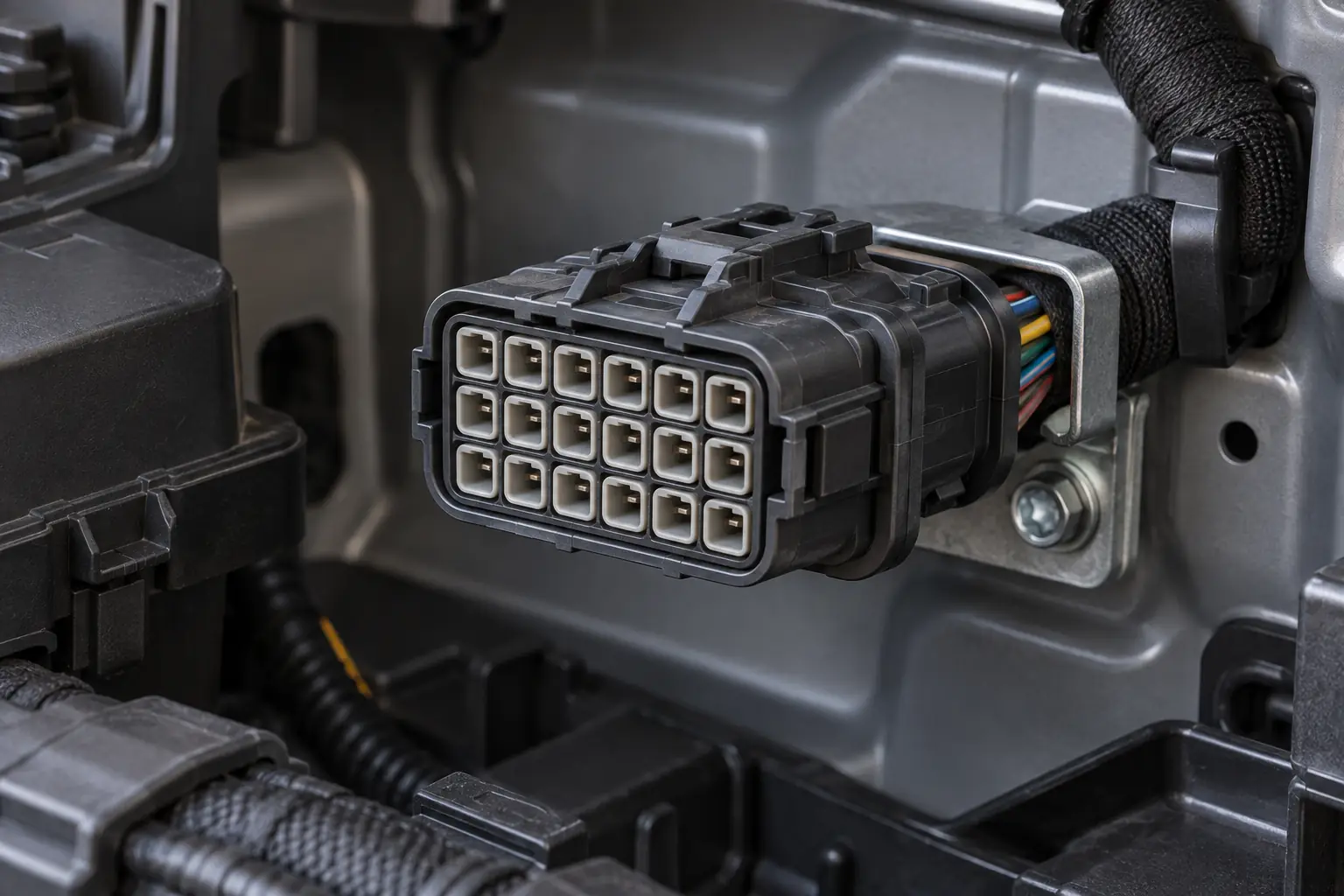
It is used when a module or harness branch needs many power, ground, signal or communication circuits in one removable interface. Body, seat, door, HVAC and lighting functions are possible, but the circuit mix is application-specific. Confirm all 18 cavity assignments.
How do I confirm that an 18-pin automotive connector matches my vehicle wiring?
Compare part numbers, drawings, viewing direction, keying, latch, cavity map, terminals, wire range and environment. Do not rely on shape or pin count. A guide to types of automotive wire connectors can help narrow the family before sample validation.
Do 18-pin automotive connectors need a matching male and female housing?
An inline harness connection normally needs a compatible pair; a harness plug connected to a module needs the correct housing for its header. Because housing and contact gender may be described differently, verify the mate by part number and drawing.
What terminal and wire-gauge options are common for an 18-pin automotive connector?
Crimped tab and receptacle contacts are common, sometimes in hybrid layouts with multiple contact sizes. No gauge range is universal to all 18-position housings. Use the terminal drawing to verify conductor area, insulation diameter, current, temperature, plating and tooling.
When should I choose a sealed 18-pin automotive connector?
Choose sealing when the location faces splash, road spray, dust, condensation or fluids. Verify the complete mated assembly, wire seals and cavity plugs; protection is not established by the housing alone.
Can I replace one terminal in an 18-pin connector without replacing the full housing?
Often yes, if the cavity, latch, secondary lock and seals remain undamaged and an approved terminal is available. Follow the correct process for depinning an automotive connector, then verify crimp, retention, cavity map and continuity. Replace a heat-damaged, cracked or non-retaining housing.
Which Sources Support This Selection Guidance?
- SAE International, SAE/USCAR-2: Performance Specification for Automotive Electrical Connector Systems
- ISO 8092-2:2023, Road vehicles—Connections for on-board electrical wiring harnesses—Part 2
- IEC 61984:2008, Connectors—Safety requirements and tests
- Fluke, A Guide to Continuity Testing with a Multimeter
The decisive detail is rarely the number of cavities; it is whether the drawing, mating pair, termination process and validation evidence all describe the same interface.
To discuss sourcing, review the ZUCH product range and contact the team with your connector drawings, wire specifications, circuit map and test requirements for an 18 pin automotive connector.