PCB Header Coplanarity and Solder Reliability in Automated Assembly
Solder joints on a multi-lead header form reliably only when every lead sits within the agreed coplanarity limit at the machine. Control the limit, the packaging and the incoming check, not just the reflow profile.
For a related technical topic, see PCB Header Pitch Selection: Matching Current, Density and Assembly Process.
Contents
Part 1. What is coplanarity and why does it drive solder quality?
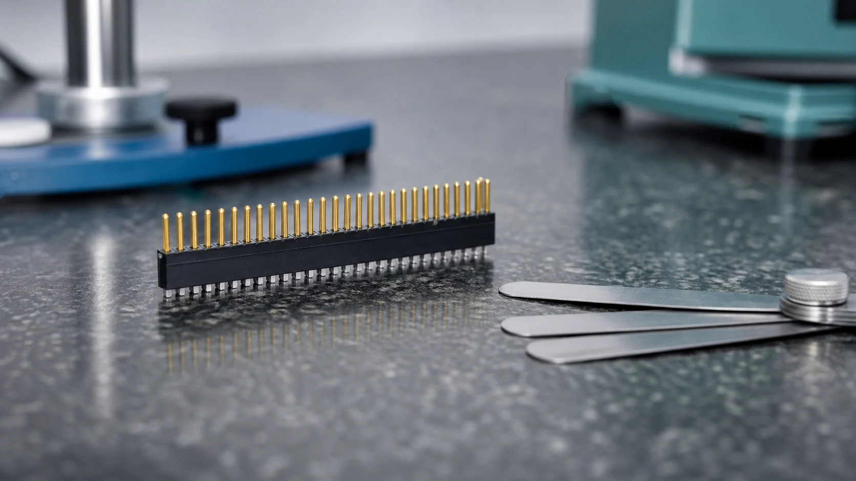
Coplanarity describes how far individual leads or solder surfaces deviate from a common seating plane. A lifted lead bridges the paste gap poorly or not at all, so the deviation budget directly limits open-joint and weak-joint risk in automated soldering.
| Control point |
Question to settle |
Owner |
| Specification |
Limit value and datum definition |
Design and supplier jointly |
| Verification |
Method, sample plan, records |
Incoming quality |
| Preservation |
Packaging and handling rules |
Supplier and logistics |
Part 2. How do coplanarity defects appear in production?
Typical signatures are opens or starved fillets on the lifted leads, inconsistent joint shapes along one row, or headers that rock on the board before soldering. Inspection may catch them, but escapes tend to fail later under thermal or mechanical stress.
Part 3. Which header design and packaging features protect coplanarity?
Moulded lead alignment, robust lead geometry and tray or tape packaging that supports the leads all reduce deformation between moulding and placement. Review how the parts are carried, separated and presented to the machine, because handling is where geometry is lost.
Part 4. How should incoming inspection measure coplanarity?
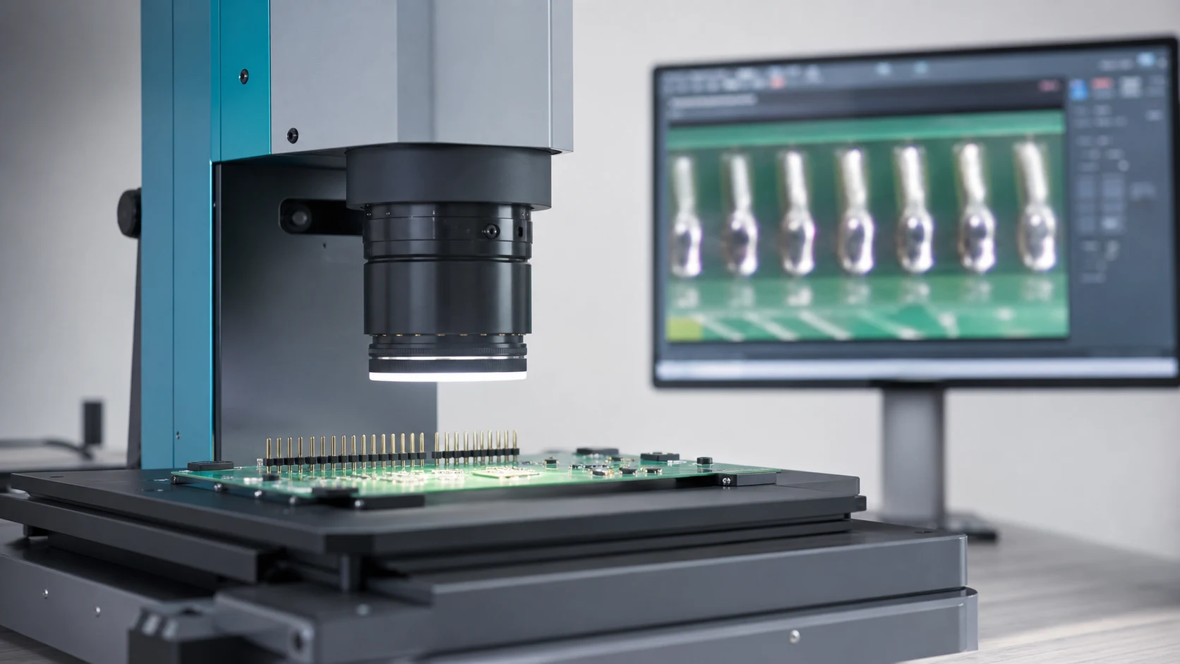
Agree the measurement method, datum plane, sample plan and limit with the supplier, whether the check uses a flat reference plate or an optical system. Keep the method identical on both sides so results can be compared without dispute.
| Defect signature |
Likely cause |
First response |
| Opens on one row |
Lifted leads or tilted seating |
Re-measure coplanarity on the lot |
| Starved fillets |
Marginal lead height over paste |
Review limit versus paste height |
| Rocking part |
Bent leads from handling |
Audit packaging and presentation |
Part 5. How do rework and manual handling affect joint reliability?
Manual straightening of bent leads changes the local metallurgy and rarely restores the original geometry precisely. Define which deviations may be reworked, by whom and with what re-inspection, and route the rest through nonconformance disposition.
Important: General guidance cannot approve a specific design or lot. This is a source-note application of the IPC and TE Connectivity references listed below; apply it through your controlled drawing and acceptance plan.
Part 6. What should buyers agree with the supplier before ramp?
Close the coplanarity limit, measurement method, packaging specification, process capability expectations and the reaction plan for violations. Put these in the quality agreement so volume production inherits the controls automatically.
Part 7. Which ZUCH route supports an assembly-quality inquiry?
Use ZUCH’s innovation route and the live product catalogue to identify relevant connector, terminal or housing component families. These are discovery routes only and do not demonstrate that a specific configuration is approved for your application.
RFQ inputs
- Coplanarity limit, datum definition and measurement method.
- Packaging specification and handling rules through placement.
- Process capability evidence and inspection records format.
- Nonconformance reaction plan and rework boundaries.
Fit Boundary
This guide supports engineering and sourcing discussion; it cannot replace programme-specific validation, market requirements, or an approval record. Use ZUCH’s sample request route or contact page for controlled component documentation and samples.

FAQ
What does coplanarity mean for a PCB header?
It is the deviation of lead solder surfaces from a common seating plane, which determines whether every lead can form a proper joint.
How much coplanarity deviation is acceptable?
The limit is design and process specific; agree a numeric limit with the supplier and assembler instead of assuming a generic value.
What solder defects does poor coplanarity cause?
Mostly opens and starved or inconsistent fillets on lifted leads, which may escape inspection and fail later in service.
How is coplanarity measured at incoming inspection?
Against an agreed datum using a reference-plate or optical method, with a documented sample plan shared with the supplier.
Can bent header leads be straightened and used?
Only within a defined rework rule with re-inspection; uncontrolled straightening degrades geometry and joint reliability.
Does packaging really influence coplanarity?
Yes. Trays, tape and separators that support leads preserve geometry; loose or mixed packaging is a common deformation source.
What coplanarity topics belong in an RFQ?
Limit and datum, measurement method, packaging, capability evidence, records and the reaction plan for violations.
References
 Zhejiang ZUCH Technology Co., Ltd.