Pin Header vs Socket Header: When Each Board Connection Makes Sense
Decide which board carries pins and which carries sockets from wear, exposure and service logic, not habit. The pair works as one interface, so specify both halves together.
Contents
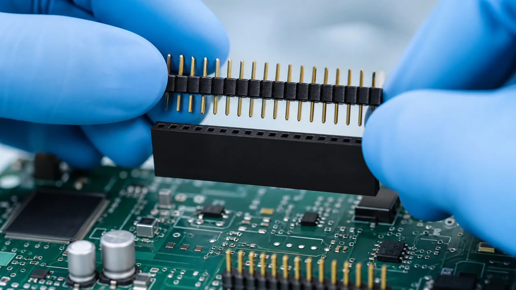
A pin header presents exposed male contacts; a socket header carries the sprung female contacts that grip them. Electrical behaviour comes from the mated pair, so the two halves should be selected and documented as one interface.
| Attribute |
Pin header side |
Socket header side |
| Contact exposure |
Exposed pins, easier to touch or bend |
Recessed contacts, better protected |
| Wear behaviour |
Handling and bending damage |
Spring relaxation over cycles |
| Typical placement |
Side that is unpowered or protected |
Side that stays powered or faces handling |
Which side of the interface should carry the sockets?
A common practice is to put sockets on the side that stays powered or that faces handling, because recessed female contacts are harder to touch or bend. Confirm the rule against your own safety review and assembly flow instead of copying it blindly.
How do mating cycles and wear split the decision?
Wear concentrates in the sprung socket contacts, while pins suffer more from bending and handling damage. Place the more easily replaced or cheaper half on the side that sees frequent disconnection, and state the expected cycle scenario in the drawing.

How do retention and polarization options differ?
Friction fit, latches, shrouds and polarizing walls are distributed differently across pin and socket families. Choose the combination that survives your vibration, service and mis-mating risks, and verify the features exist in both halves you specify.
| Feature |
What it protects against |
Check before release |
| Shroud or wall |
Bent pins and side loads |
Fits mating half and assembly tools |
| Latch or friction lock |
Vibration back-out |
Engagement with chosen counterpart |
| Polarizing key |
Reversed mating |
Present and aligned in both halves |
What electrical review applies to both options?
Current, voltage spacing, contact plating and temperature rise belong to the mated pair under application conditions. Treat any single-side figure as an input to review, not as an approval of the interface.
Important: General guidance cannot approve a specific design or lot. This is a source-note application of the IPC and TE Connectivity references listed below; apply it through your controlled drawing and acceptance plan.
How should the decision be documented for sourcing?
Record both part definitions, the mating logic, cycle expectations, retention features and the acceptance checks for the pair. Give suppliers the interface context so substitutions are evaluated against the real application. For a related technical reference, see Plug vs Receptacle Connectors: A Design Guide for Mating Interfaces.
Use ZUCH’s PCB Header category and the live product catalogue to identify relevant connector, terminal or housing component families. These are discovery routes only and do not demonstrate that a specific configuration is approved for your application.
RFQ inputs
- Interface definition covering both halves and the mating logic.
- Cycle scenario, vibration exposure and retention requirements.
- Electrical duty for the mated pair and plating expectations.
- Samples of both halves plus the acceptance checks for the pair.
Fit Boundary
This guide supports engineering and sourcing discussion; it cannot replace programme-specific validation, market requirements, or an approval record. Use ZUCH’s sample request route or contact page for controlled component documentation and samples.
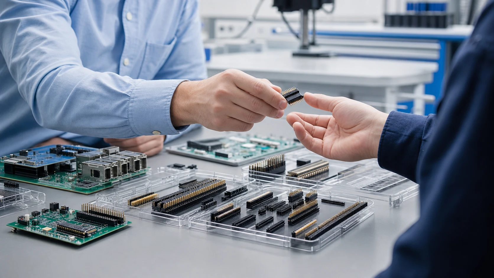
Pin and socket headers are mating halves, not universal substitutes. The decision depends on which side should expose or protect contacts, how often the interface will be serviced, how polarity and retention are controlled, and whether both halves are qualified as one mating system.
| Decision area |
Pin header question |
Socket header question |
| Contact protection |
Can exposed pins be protected from handling, shorts, and misalignment? |
Does the socket housing shield contacts and guide the mating part? |
| Service |
Will the board or cable side be replaced more often? |
Which side should remain with the serviceable harness or module? |
| Mating control |
What keying, shroud, latch, and orientation are required? |
Does the receptacle accept the specified pin geometry and retention? |
| Qualification |
Are both halves from an approved compatible family? |
Are cycle, current, voltage, and environmental limits defined for the pair? |
FAQ
Which side should be the socket in a powered system?
There is no universal rule. Place the protected contact side where handling, shorting, or service risk is greatest, then confirm the enclosure, keying, retention, and mating procedure for the complete interface.
Do pin and socket headers wear at the same rate?
Not necessarily. Contact geometry, normal force, plating, alignment, contamination, insertion speed and the mating counterpart all influence wear. Use the paired product data and test conditions.
Can I buy the two halves from different suppliers?
Only after verifying mechanical, electrical, material, plating, keying, retention, cycle, and environmental compatibility. A similar pitch or pin count is not proof of interchangeability.
How do I prevent reversed mating between similar headers?
Use documented polarization, keying, shrouds, cavity coding, orientation marks, and a verified mating drawing. Confirm that the chosen feature remains visible and usable during assembly and service.
What is the difference between a pin header and a socket header?
The pin header carries exposed male contacts and the socket header carries sprung female contacts; they function only as a mated pair.
Which side should be the socket in a powered system?
A frequent practice is to socket the powered or handled side because recessed contacts resist touch and damage, subject to your own safety review.
Do pin and socket headers wear at the same rate?
No. Sockets accumulate spring wear across cycles while pins are more exposed to bending and handling damage.
Can I buy the two halves from different suppliers?
Only with an interface review: geometry, plating and retention features must be confirmed compatible for the mated pair.
How do I prevent reversed mating between similar headers?
Use polarizing walls, keys or shrouds present in both halves, and verify them on samples before release.
Does board orientation change the choice?
It can. Mating direction, access and support affect insertion force handling and which side risks damage during service.
What should a pin and socket header RFQ include?
Both part definitions, mating and cycle expectations, electrical duty, retention features, samples and acceptance checks for the pair.
Pin-versus-socket selection is an interface decision. Qualify the two halves together for protection, keying, retention, electrical load, service cycles, and environment instead of assuming that matching pitch makes a pair interchangeable.
References
 Zhejiang ZUCH Technology Co., Ltd.