Wafer Connectors: A Practical Guide to Board-to-Wire Applications
A wafer connector links a board header to a crimped-wire housing, so the interface is only as good as all three elements together. Define board side, wire side and locking as one system.
Contents
Part 1. What is a wafer connector in a board-to-wire system?
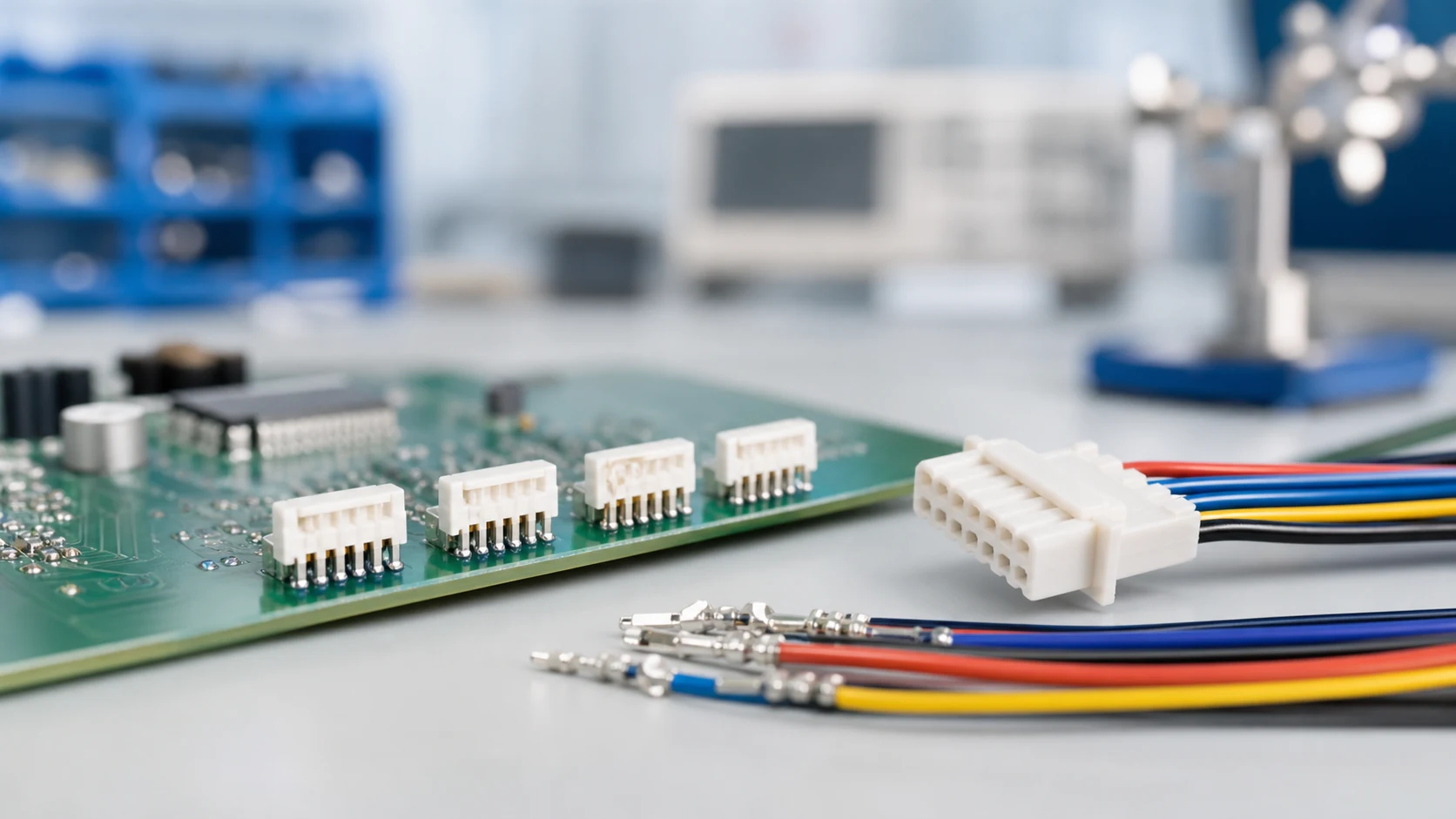
In common usage the wafer is the board-mounted header whose contacts mate with a wire-side housing carrying crimped terminals. It converts board circuits into a serviceable wire interface for internal power, signal and sensor runs. For a related technical reference, see Pin Header vs Socket Header: When Each Board Connection Makes Sense.
| System element |
Key decisions |
Failure risk if skipped |
| Board header |
Pitch, orientation, solder interface |
Layout rework or weak joints |
| Wire housing |
Circuit map, locking, polarization |
Back-out or mis-mating |
| Crimped terminals |
Wire range, tooling, inspection |
Unstable contact resistance |
Start from circuit count, current and voltage per circuit, wire sizes, mating orientation and available board space. Add environment, service expectations and the assembly method, because those inputs later decide locking, plating and pitch.
Part 3. How do pitch, circuits and current interact?
Finer pitch shrinks the footprint but reduces contact size and heat spacing, so high-current circuits may need a coarser pitch or distributed loading. Confirm the combination with a temperature-rise review under the real load pattern rather than a single-contact figure.
Part 4. How do locking and retention features change service behaviour?
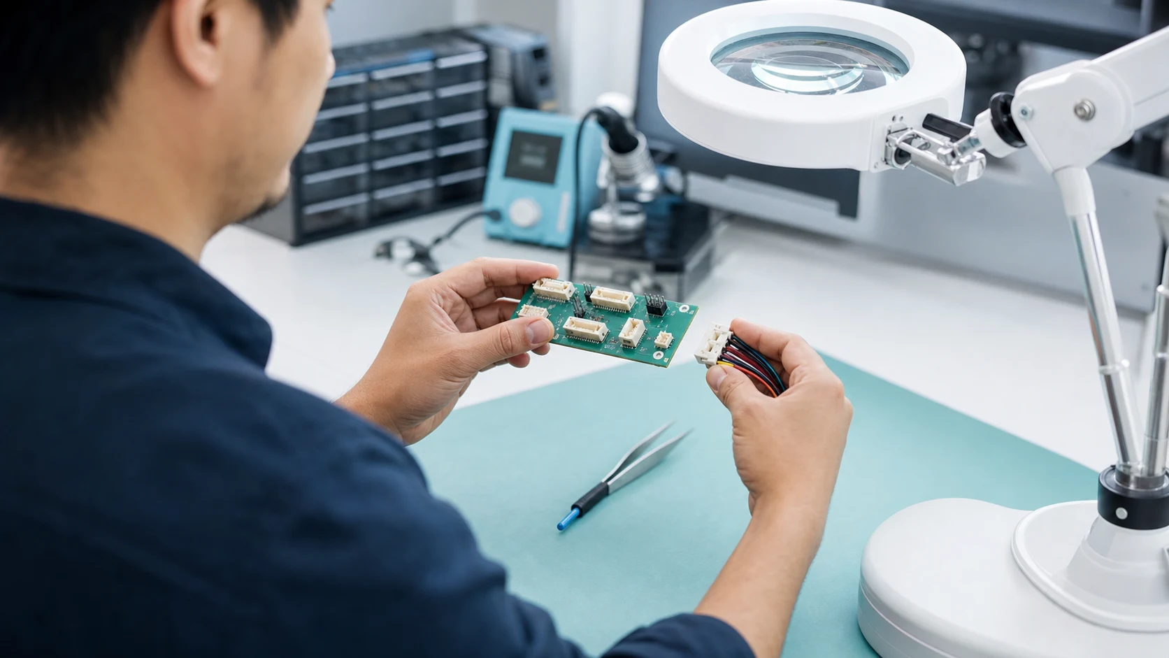
Friction-only interfaces are compact but vulnerable to vibration back-out; positive locks add security and a defined removal action. Match the retention style to vibration exposure and to how often service will disconnect the interface. For a related technical reference, see Wafer Connector vs FFC/FPC Connector: Selecting for Vibration and Service Access.
| Retention style |
Behaviour in service |
Typical fit |
| Friction only |
Compact, no removal action |
Protected, low-vibration locations |
| Positive lock |
Defined engagement and release |
Vibration exposure or frequent service |
| Lock plus strain relief |
Load kept off contacts |
Cable movement near the interface |
Part 5. How should the crimped-wire side be controlled?
Crimp quality lives in tooling, wire preparation and process monitoring, and it determines the interface’s electrical stability. Require the terminal-to-wire combination, tooling references and inspection criteria to be documented in the build package.
Important: General guidance cannot approve a specific design or lot. This is a source-note application of the IPC and TE Connectivity references listed below; apply it through your controlled drawing and acceptance plan.
Part 6. What belongs in the validation and release plan?
Validate representative assemblies for mating behaviour, retention, electrical stability and any environmental exposures the design claims. Name samples, methods, limits and records, and define which changes reopen the validation.
Part 7. Which ZUCH route supports a wafer connector inquiry?
Use ZUCH’s Small Pitch Connectors category and the live product catalogue to identify relevant connector, terminal or housing component families. These are discovery routes only and do not demonstrate that a specific configuration is approved for your application.
RFQ inputs
- Circuit map with current, voltage and wire sizes per position.
- Pitch, orientation, locking and polarization requirements.
- Crimp tooling references, inspection criteria and records.
- Validation scope, samples, limits and change triggers.
Fit Boundary
This guide supports engineering and sourcing discussion; it cannot replace programme-specific validation, market requirements, or an approval record. Use ZUCH’s sample request route or contact page for controlled component documentation and samples.
FAQ
What is a wafer connector?
A board-mounted header in a board-to-wire pair that mates with a crimped-wire housing, carrying internal power or signal circuits.
Where are wafer connectors typically used?
Inside equipment where board circuits must reach wired subassemblies, such as sensors, fans, panels and internal power runs.
How do I choose the pitch for a wafer interface?
Balance footprint limits against current per circuit and process capability, then confirm thermally with the real load pattern.
Do wafer connectors need a locking feature?
Not always, but vibration exposure or service handling usually justifies a positive lock; the drawing should state the decision.
Why does crimp quality matter so much here?
The crimp sets the wire-side electrical stability; poor tooling control produces intermittent faults that appear later in the field.
Can one wafer family cover both signal and power circuits?
Sometimes, using distributed loading or mixed contact arrangements, but the combination must pass its own electrical and thermal review.
What should a wafer connector RFQ contain?
The circuit map, mechanical and locking requirements, crimp documentation, validation plan and required records.
References
 Zhejiang ZUCH Technology Co., Ltd.