Zhejiang ZUCH Technology Co., Ltd.
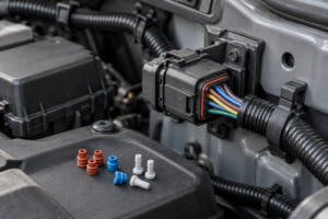
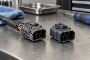
When a harness engineer in a new vehicle program connects a replacement sensor branch, the first visible failure can be simple: the plug clicks in, but one circuit does not operate. A pin count alone did not identify the correct part. The root cause is usually a mismatch in cavity numbering, terminal family, keying, wire range, or environmental protection. Treating the connector as an interface specification, rather than a five-position plastic housing, prevents that failure before samples reach the line.
Summary: A 5 pin automotive connector is suitable only when its pinout, mating geometry, terminals, wire range, retention, and environment match the harness. Five cavities do not imply a standard pin assignment or universal interchangeability. Start with the vehicle drawing and mating half, verify every cavity and terminal, then select sealing and validation evidence; ISO 8092 addresses road-vehicle wiring-harness connections, while connector performance specifications such as USCAR-2 define test expectations rather than granting a blanket product certification.
What “5-pin” tells you—and what it does not
“Five-pin” describes the number of contact positions in a housing. It does not identify the circuit function, terminal size, gender, keying, latch location, or sealing system. A five-position housing may serve a sensor, relay, actuator, lighting subassembly, or accessory circuit, with very different current, signal, and packaging requirements.
Begin with the controlled drawing, service part number, or the original mating connector. Record the connector family, cavity numbering view (wire side or mating face), key code, secondary lock, terminal part number, and any cavity plugs or seals. A photograph is useful for orientation, but it is not enough evidence for a production substitution because two housings can look similar while using different terminals.
Pin count also does not establish a pinout. One program may use power, ground, signal, and diagnostic circuits; another may use five low-current signal paths. Never bridge or repurpose a cavity based on color alone. Confirm circuit identity against the wiring diagram and check continuity with the connector disconnected and the circuit made safe.
Compare common five-position connector choices
The most useful early decision is not “which five-pin part is cheapest?” It is “which interface and environment must remain stable through production and service?” The comparison below keeps the decision at architecture level; actual ratings must come from the selected terminal and housing data sheet.
| Choice | Where it can fit | Benefits | Checks before approval |
|---|---|---|---|
| Unsealed five-position housing | Protected cabin, module, or enclosed harness zones | Smaller package and simpler assembly when water and dust are controlled | Confirm the installation remains outside splash, washdown, condensation, and fluid paths; verify terminal retention and strain relief |
| Sealed five-position housing | Engine-bay, underbody, exterior, or other exposed routing | Can limit ingress when the complete system is assembled correctly | Match wire seals, cavity plugs, seal diameter, latch, and specified environmental tests; do not infer an IP rating without a test basis |
| Single-key or keyed family | Harnesses where mis-mating must be prevented | Guides assembly and can prevent a visually similar but incorrect mate | Confirm key code, polarization, mating half, and service replacement availability |
| Housing with secondary terminal lock | Production harnesses subject to vibration and service handling | Provides an additional retention step after terminals are inserted | Check terminal insertion position, lock engagement, extraction procedure, and inspection criteria |
Verify the electrical and mechanical interface
Map the pinout from the correct viewing direction
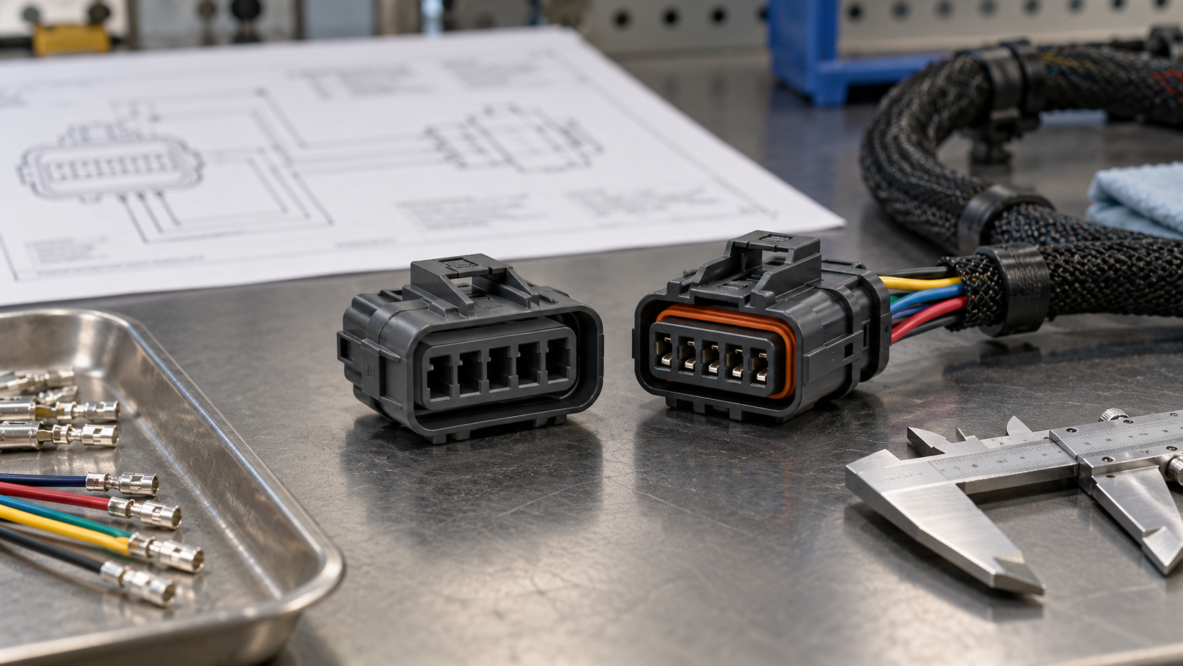
Pin numbering is commonly shown from the mating face, while harness work is performed from the wire side. Mark the reference view on the drawing and photograph, then map cavity numbers to circuit names. The check should include power and return paths, sensor references, shields or drains where applicable, and any unused cavity. A continuity check confirms assembly; it does not prove that the circuit is correctly protected or that the contact system is rated for the load.
Match the terminal and conductor system
The terminal is the electrical interface. Confirm its contact style, plating, crimp wings, insulation support, and approved conductor range. Wire gauge must be selected with the terminal specification and the circuit’s current, temperature, voltage drop, and bundling conditions in mind. Avoid copying a gauge from a visually similar connector. A terminal that accepts a conductor mechanically may still fail crimp-height, pull-force, or electrical-resistance requirements.
For a new harness, define the applicator, crimp settings, inspection method, and sample retention plan before release. The practical sequence in this automotive terminal crimping guide can support a process review, but the terminal maker’s application specification remains controlling.
Check mating and package constraints
Measure the available envelope, cable exit direction, latch access, bend radius, and service clearance. Verify that the selected male and female halves are a qualified mating pair; “male” and “female” descriptions alone do not establish compatibility. Keying, polarization ribs, terminal positions, and CPA or secondary-lock features must agree. If the connector is mounted to a module, include bracket, PCB, or panel tolerances in the interface review.
Choose sealing, wire range, and retention deliberately
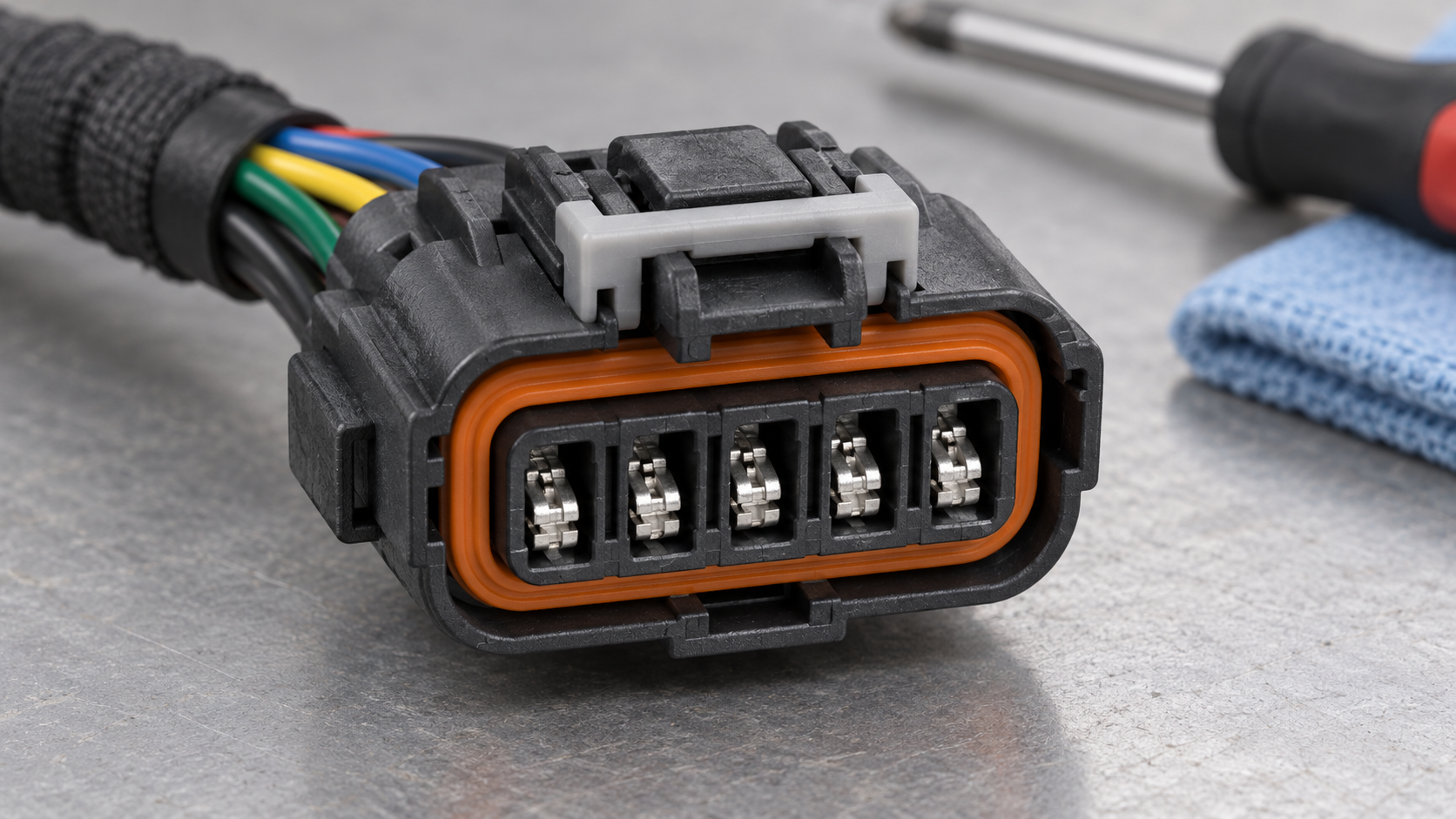
Use a sealed design when the installation has a credible exposure route: spray, splash, mud, dust, condensation, or fluid contact. Sealing is a system property. The housing, wire seal, cavity plug, terminal, cable diameter, mating interface, and assembly process must all be compatible. A sealed housing used with the wrong seal diameter is not a sealed harness, and an untested assembly should not be marketed with an IP claim.
Retention deserves the same attention as ingress. Confirm primary terminal lance engagement, secondary lock position, connector latch force, and the service method for releasing a terminal. A damaged terminal or housing may be replaceable, but only if the replacement uses the same qualified family and the wire and crimp remain within specification. See the broader automotive connectors and terminals overview when documenting the complete contact system.
| Selection step | Evidence to collect | Release question |
|---|---|---|
| 1. Identify the interface | Mating-half part number, drawing, cavity view, key code, connector orientation | Can a technician identify the correct mate without relying on color or appearance? |
| 2. Define circuits | Pinout, circuit function, fuse or driver context, unused-cavity status | Does every cavity have a documented purpose or approved plug? |
| 3. Select contacts | Terminal number, plating, conductor range, crimp specification, applicator | Are wire gauge and crimp controls supported by the terminal documentation? |
| 4. Set environment | Exposure map, seal and cavity-plug data, temperature and fluid assumptions | Is sealing necessary, and is the complete assembly testable for the claimed environment? |
| 5. Confirm retention and service | Primary/secondary lock details, latch operation, extraction tool, repair policy | Can production and service teams inspect, repair, and replace the interface consistently? |
Apply standards without overclaiming compliance
ISO 8092 provides requirements and terminology for connections used in road-vehicle wiring harnesses; use the applicable part and edition for the program. USCAR-2 is a performance specification for automotive electrical connector systems and is commonly used to structure tests such as mechanical, electrical, environmental, and durability evaluations. It is not a universal “approved connector” label. SAE J2030 addresses heavy-duty electrical connector performance and may be relevant to heavy-duty vehicle applications, but it should not be presented as a requirement for every passenger-car five-pin connector.
Ask the supplier to identify the exact test method, sample configuration, conditioning, acceptance criteria, and report revision. Certification claims also need scope. ZUCH states IATF 16949:2016, CNAS laboratory accreditation, UL witness laboratory capability, and UL/CUL coverage, with PA66 or PA66 GWT materials where applicable; these statements do not automatically certify every five-pin configuration. Request the product-specific drawing, material designation, terminal specification, and validation evidence for the part being quoted. The rectangular connector range is one place to compare available housing families, but final fit remains drawing-led.
A practical procurement workflow
- Freeze the reference: photograph and identify the installed mating half, then record the view used for cavity numbering.
- Build the interface sheet: list cavity, circuit, terminal, conductor range, seal, key, lock, and mating part for all five positions.
- Screen the environment: classify cabin, protected module, engine-bay, underbody, or exterior exposure before choosing sealed or unsealed.
- Validate the process: approve crimp tooling, pull-force and crimp-height checks, terminal retention checks, and assembly inspection criteria.
- Approve evidence: compare drawings and test reports, then release a controlled part number and change process. Browse the wider ZUCH product catalog only after the interface requirements are defined.
Frequently asked questions
What is a 5-pin automotive connector typically used for in sensors, relays and accessory circuits?
It can carry five separate circuits in a sensor, relay, actuator, lighting, or accessory branch. The pin count does not define the function or current capability, so the wiring diagram and terminal specification must identify each circuit before substitution.
How do I confirm that a 5-pin automotive connector matches my vehicle wiring?
Compare the mating housing, keying, cavity numbering view, terminal family, wire range, and pinout against the vehicle drawing or service information. Then verify continuity with the circuit isolated; a connector that physically mates can still have a different cavity assignment.
Do 5-pin automotive connectors need a matching male and female housing?
Yes, a separable harness connection requires a qualified mating pair, although terminology varies by connector family. Match the exact housing series, key, terminal positions, seals, and locks rather than ordering a generic male and female by pin count.
What terminal and wire-gauge options are common for a 5-pin automotive connector?
Options depend on the housing family and circuit duty; common designs use stamped-and-formed crimp terminals with a specified conductor range. Select wire gauge from the terminal application data and electrical design, then confirm crimp height, pull force, contact resistance, and temperature assumptions.
When should I choose a sealed 5-pin automotive connector?
Choose sealing when the installed interface can see water, spray, dust, mud, condensation, or fluids. Confirm that wire seals, cavity plugs, cable diameter, housing, and mating interface are a qualified set, and use an environmental rating only when the assembled system has supporting test evidence.
Can I replace one terminal in a 5-pin connector without replacing the full housing?
Often, yes, if the housing is undamaged and the replacement terminal is the same qualified part for the conductor and seal. Follow the service procedure, use the correct extraction and crimp tools, inspect primary and secondary retention, and replace the housing when locks, cavities, or seals are compromised.
References
- ISO 8092-1, Road vehicles — Connections for on-board electrical wiring harnesses (International Organization for Standardization).
- USCAR-2, Performance Specification for Automotive Electrical Connector Systems (SAE International).
- SAE J2030, Heavy-Duty Electrical Connector Performance Standard (SAE International).
- IEC 61984, Connectors — Safety requirements and tests (International Electrotechnical Commission).
Conclusion
Finding the right five-position connector is an interface-control exercise, not a pin-count search. Confirm the mating family and cavity view, map every circuit, select the terminal and conductor together, and decide sealing from the real installation environment. Then verify retention, tooling, serviceability, and the test evidence behind any environmental or compliance claim. This sequence reduces rework because it catches look-alike housings and incomplete substitutions before a harness reaches production. ZUCH’s connector portfolio and engineering documentation can support a drawing-led review; use the product catalog to start a qualified part discussion and contact the team with your mating connector, pinout, wire range, exposure conditions, and annual volume. The durable rule is simple: five cavities identify a format, while the complete interface specification identifies the right part.