Zhejiang ZUCH Technology Co., Ltd.
Production approval often reaches the sourcing desk with a connector drawing, a few passing samples, and a statement that the part has been “tested.” That package can still hide a serious gap: the sample identity may not match the released construction, an electrical check may prove continuity but not contact stability, or an environmental report may use conditions unrelated to the vehicle mounting zone. The visible failure may appear only after vibration, heat, moisture, or a supplier change—and then containment, harness rework, and launch disruption cost far more than the original test program. The central issue is therefore not whether a connector passed one test. It is whether the correct part completed a controlled, risk-based sequence with acceptance criteria tied to the applicable customer specification and vehicle documentation.
Quick Answer: Before production approval, verify drawing and sample identity; inspect dimensions, terminals, seals, and assembly; establish continuity and contact-resistance baselines; check retention and mating behavior; apply vibration, temperature, fluid, or sealing exposure only as required by the mounting risk and governing specification; then repeat the relevant electrical and visual checks. A complete automotive connector validation package also links samples, equipment, results, deviations, and approvals to a controlled revision. USCAR2-8 covers performance testing of low-voltage and coaxial road-vehicle connection systems, while ISO 8092-2 and the IEC 60512 series provide additional test-method context. Exact severities, sequence, sample size, and pass/fail limits must come from the applicable OEM or customer requirement and product drawing.
A Step-by-Step Validation Sequence Before Production Approval
A useful plan begins with evidence control, not the test chamber. The team should first freeze the part number, drawing revision, bill of materials, tooling state, crimp setup, wire type and size, cavity population, seal configuration, and supplier process represented by each sample. Without that identity chain, even a technically sound report may not support the released production part. Buyers who need a broader terminology review can start with this guide to automotive electrical connectors.
The sequence below is deliberately limit-free. It shows the decision logic; the controlling specification supplies the test order, conditioning, quantities, measurement method, and acceptance limits.
- Identity: confirm that the part and drawing revision, material or component references, wire and crimp setup, and sample traceability represent the intended construction.
- Dimensional and assembly checks: inspect terminals, housings, seals, locks, interfaces, and critical dimensions before destructive or time-consuming exposure.
- Electrical baseline: record continuity and the specified contact-resistance measurement, including fixture or lead-compensation details where applicable.
- Mechanical interface: document retention, insertion/withdrawal or mating-force data, and lock engagement under the controlling method.
- Risk-based environment: run only the applicable vibration, thermal, humidity, fluid, immersion, spray, or sealing sequence for the mounting zone and classification.
- Post-stress recheck: repeat the required electrical, visual, sealing, and mechanical measurements, and investigate every anomaly.
- Controlled approval: link signed results, deviations, calibration status, sample disposition, approval, and change control to the released construction.

What Electrical, Retention, and Mating Tests Confirm
Why Continuity and Contact Resistance Are Different Checks
Continuity answers a binary circuit question: is there an electrical path under the stated test setup? It can detect an open circuit, an incomplete connection, or an intermittent condition when the monitoring method is suitable. It does not, by itself, quantify the quality or stability of the contact interface.
Contact-resistance measurement evaluates the voltage-current behavior of a defined connection under a specified method. The fixture, measurement points, current level, instrument resolution, wire contribution, and temperature all affect interpretation. In sound automotive connector testing, the baseline is recorded before stress and the applicable measurement is repeated afterward; the governing customer specification decides what change or absolute value is acceptable. A report that lists only “pass” without the method, points, and criteria is difficult to audit.
What a Terminal Retention Test Must Confirm
A terminal retention test examines whether the contact remains seated in its housing under the defined axial loading method. The sample state matters: the primary lance, secondary lock, seal, wire attachment, cavity, loading direction, pull rate, and any preconditioning must match the applicable procedure. Testing the contact alone is not equivalent to testing the assembled contact-housing system.
Retention evidence should be read alongside assembly inspection. A high recorded force does not excuse a partially seated terminal, damaged locking feature, incorrect cavity, or unverified secondary lock. For additional design and inspection context, see the female terminal contact retention guide.
Why Mating Force and Mating-Cycle Durability Matter
Mating and unmating force affect assembly ergonomics, lock engagement, serviceability, and the risk of incomplete connection. Cycle testing can also reveal wear, loss of normal force, seal damage, or housing distress that a single mating event will not show. The number of cycles and force limits must come from the customer specification or drawing; they should never be borrowed from a visually similar connector.
| Check | What it can demonstrate | What it cannot demonstrate alone | Commercial value of the evidence |
|---|---|---|---|
| Continuity | A circuit path exists under the stated monitoring conditions | Low or stable contact resistance, environmental endurance, or correct terminal seating | Fast screening for opens and specified intermittency |
| Contact resistance | Baseline connection behavior and change after conditioning | Housing retention, sealing, or vehicle-level compatibility | Helps reveal degradation that simple continuity may miss |
| Terminal retention | Resistance to contact displacement in the tested housing condition | Electrical stability throughout vehicle life or correct mating geometry | Reduces risk of terminal push-out and assembly escapes |
| Mating/unmating force | Interface force and lock engagement behavior under a defined setup | Durability after repeated cycles unless cycling is included | Supports assembly and service process decisions |
| Environmental exposure plus recheck | Change caused by the specified vibration, temperature, fluid, or sealing stress | Suitability for an untested mounting zone or stress profile | Targets field-risk mechanisms before release |
When to Run Vibration, Temperature, and Sealing Tests
Automotive environmental testing should follow the intended mounting location, circuit role, connector classification, and customer requirement. A dry cabin connector and an underbody sealed connection do not face the same temperature range, vibration input, water exposure, chemicals, or mechanical support. “Automotive grade” is therefore not a test plan. The approval team should map each foreseeable stress to a governing requirement and document why a test is included, modified, or excluded.
| Application evidence | Risk questions to ask | Candidate validation families | Approval decision needed |
|---|---|---|---|
| Protected interior location | What are the actual thermal range, vibration path, handling, and contamination risks? | Electrical baseline, mechanical checks, specified thermal and vibration conditioning | Confirm that exclusion of sealing or fluid tests is supported by the vehicle requirement |
| Door, body, or intermittently wet area | Can splash, condensation, harness movement, or pressure change reach the interface? | Specified sealing, humidity, thermal cycling, vibration, and post-stress electrical checks | Match seal configuration and test orientation to the installed assembly |
| Engine-compartment or elevated-temperature zone | Which heat sources, fluids, vibration inputs, and harness loads apply? | Customer-specified temperature, vibration, fluid compatibility, sealing, and remeasurement | Verify that the exact material and wire construction tested is the released construction |
| Underbody or directly exposed location | Are immersion, spray, debris, fluids, thermal shock, or high vibration credible? | Applicable high-severity sealing, mechanical, thermal, chemical, and electrical sequence | Use the vehicle-program classification and installation orientation, not a generic sealed label |
| Safety-relevant or diagnostic-sensitive circuit | What are the consequences of an intermittent or resistance increase? | Specified monitoring during stress, post-stress measurements, and enhanced traceability | Obtain customer concurrence for the sequence and acceptance criteria |
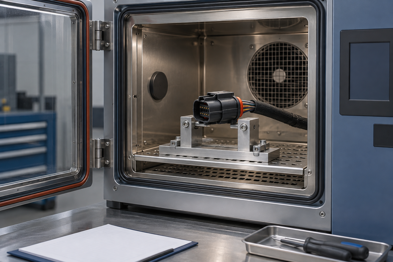
Vibration should be applied with representative fixtures, harness support, orientation, and monitoring when the controlling procedure requires it. Temperature cycling should represent the specified extremes and transitions rather than an assumed “typical” profile. A sealing test must define the mated state, wire and cavity population, plugs, seals, orientation, pressure or immersion conditions, and inspection method. After each required sequence, the team should repeat the specified electrical, visual, mechanical, or leak checks; otherwise, exposure data alone says little about retained function.
Which Documents Should Define Test Acceptance
Approval becomes unreliable when a test-method document is treated as a universal product certificate. Procurement and engineering should separate three layers:
- Performance specifications define qualification logic, test groups, conditioning, and performance expectations for a stated scope. USCAR2-8, for example, addresses performance testing of low-voltage and coaxial road-vehicle electrical connection systems. ISO 8092-2 addresses definitions, test methods, and general performance requirements for connections used in on-board vehicle wiring harnesses. Applicability still depends on the program.
- Manufacturer application specifications define how a particular terminal, seal, housing, wire, tooling, and process are to be selected and assembled. They can control strip length, crimp setup, acceptable wire range, cavity plugs, service tools, and inspection features. They do not replace an OEM performance requirement unless the customer explicitly accepts them.
- Vehicle-specific wiring documentation controls the actual circuit, connector callout, cavity assignment, wire size and type, sealing state, option content, harness routing, mounting, and approved revisions. A connector can pass a general test and still be wrong for a vehicle if this documentation is not followed.
The IEC 60512 series is a family of connector test and measurement methods. IEC 60512-1 expressly works with detail product specifications that select the applicable tests, severity, and permissible performance limits; it is not an automotive product approval certificate. Teams comparing frameworks can consult this overview of automotive connector standards, then confirm the controlling revision with the customer.
Unsupported claims create commercial risk. Calling a part “USCAR2 certified,” “ISO approved,” “waterproof,” or interchangeable without the required evidence can lead to rejected submissions, warranty disputes, containment, or loss of approved-source status. USCAR2 is a performance specification, not a third-party certification mark; a report should state the exact document revision, test scope, sample construction, deviations, and results.
How to Turn Test Results into a Production Approval Decision
- Write the validation matrix before testing. Link every requirement to its source, method, sample group, sequence, acceptance criterion, and responsible approver.
- Require raw traceability. Reports should identify the samples, drawing revision, build date or lot, laboratory, equipment and calibration status, fixtures, conditions, measured data, anomalies, and photographs where appropriate.
- Close every deviation. A deviation needs technical rationale, risk assessment, customer disposition where required, and a record of whether retesting is necessary.
- Separate component evidence from application approval. Supplier data can support the decision, but the vehicle program must approve the actual interface, wire, crimp, seal, routing, and mounting conditions.
- Put change control after approval. Material, plating, tooling, process, sub-supplier, production site, drawing, or test-method changes should trigger documented review and, where required, partial or full revalidation.
ZUCH can discuss configurable connector options and the documentation available for a sourcing review, but any product still requires approval against the buyer’s drawing, application specification, and vehicle-program requirements. The correct request is not simply “send a test report”; it is “show that this exact released construction was evaluated under our controlled requirement set.”
Frequently asked questions
Which tests should be completed before approving an automotive connector for production?
Start with sample and drawing identity, dimensional and assembly inspection, continuity and contact-resistance baselines, terminal retention and mating checks, then apply the environmental sequence required by the mounting zone and customer specification. Repeat the specified electrical, visual, sealing, or mechanical checks after stress, and close approval with traceable records and change control.
What is the difference between continuity testing and contact-resistance testing?
Continuity establishes whether an electrical path exists under the monitoring setup. Contact-resistance testing quantifies connection behavior using defined measurement points and conditions; it can reveal degradation that a simple open/closed result may not show.
How is automotive connector terminal retention tested?
The applicable procedure loads the assembled contact in a defined direction and condition while recording the required result. Housing, lock state, wire attachment, pull rate, preconditioning, and acceptance limit must follow the customer specification or product drawing rather than an assumed universal value.
When are vibration, temperature cycling, and sealing tests required?
They are required when the governing OEM or customer specification, connector classification, mounting zone, or risk analysis calls for them. The exact profiles depend on installation conditions; protected cabin, engine-compartment, and directly exposed locations should not inherit one generic sequence.
Why should mating force and mating-cycle durability be checked?
Force data helps evaluate assembly effort, lock engagement, incomplete mating risk, and serviceability. Cycling can reveal wear, seal damage, housing distress, or a change in electrical behavior, but cycle count and limits must come from the controlling requirement.
What validation records should a supplier provide before production approval?
Request the approved plan and matrix, sample and revision traceability, laboratory and equipment details, calibration status, fixtures, conditions, raw and summarized data, acceptance criteria, anomalies, deviations, failure analysis, approvals, and change history. The package should make it possible to determine exactly what was tested and whether it represents the released product.
References
- SAE International / USCAR, USCAR2-8: Performance Specification for Automotive Electrical Connector Systems (revised June 30, 2022).
- United States Council for Automotive Research, Electrical Wiring Component Application Partnership (EWCAP) Files, including specifications, revision letters, blade specifications, and report templates.
- International Electrotechnical Commission, IEC 60512-1:2018, Connectors for Electrical and Electronic Equipment—Tests and Measurements—Part 1: Generic Specification.
- International Organization for Standardization, ISO 8092-2:2023, Road Vehicles—Connections for On-Board Electrical Wiring Harnesses—Part 2: Definitions, Test Methods and General Performance Requirements.
Conclusion: approve the evidence chain, not a passing label
The decision rule is straightforward: approve a connector only when the tested sample, applicable requirement, measured result, and released production construction form one traceable chain. First confirm the drawing and application; next establish electrical and mechanical baselines; then apply only the environmental sequence justified by the vehicle mounting zone and governing customer specification; finally repeat the required checks and close every deviation. Never substitute a generic “tested” statement—or a supplier’s method report—for vehicle-program acceptance, and never carry approval across a material, plating, tooling, site, or process change without review. When procurement needs options to place into that controlled process, it can review the ZUCH connector product directory and contact ZUCH with the drawing, wire details, mounting conditions, and required documentation package.