Zhejiang ZUCH Technology Co., Ltd.
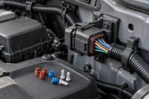
When a service technician in Detroit encountered an intermittent cooling-fan fault, the cracked plug body appeared to make a housing swap the obvious fix. After the wires were transferred, however, the fault returned during the first heat cycle. A closer inspection found discoloration at one terminal and reduced contact spring force: the visible shell damage was only part of the failure. This representative scenario shows why the decision is not simply whether a replacement housing fits. It depends on the specified connector family, terminal and seal compatibility, cavity mapping, conductor condition, and the vehicle maker’s repair procedure. SAE/USCAR-2 provides performance context, not universal repair authorization. A housing-only repair can preserve an otherwise sound harness, but it cannot restore a heat-damaged terminal, a corroded conductor, or an uncertain circuit assignment.
Quick Answer: Yes, an automotive connector housing can often be replaced without replacing the whole harness, but only when the replacement is the exact approved configuration and every existing terminal, seal, and wire is serviceable. The minimum control is a one-for-one cavity record before depinning, followed by correct insertion, primary and secondary retention checks, continuity verification, and any sealing inspection specified by the vehicle or component manufacturer. If there is heat damage, corrosion migration, weak contact force, a damaged terminal lance, overheated insulation, or an uncertain pinout, expand the repair to new terminals, a pigtail, or the affected harness section. SAE/USCAR-2 and SAE/USCAR-21 provide performance context; they do not replace vehicle-specific service information.
When Replacing Only the Connector Housing Is Reasonable
A connector housing is the molded body that positions and retains terminals and, in sealed designs, supports cavity seals, interface seals, and a secondary lock. Replacing only that body is a narrow repair: it reuses the original terminated wires. A pigtail replacement goes further by installing a connector with short wire leads and joining those leads to the vehicle harness. Replacing a harness section is broader again and may be necessary when damage has migrated beyond the connector.
A housing-only repair is defensible when four conditions are all satisfied: the housing configuration is positively identified; its cavities, keying, terminal system, seals, and secondary lock match the application; the original terminals and wires pass inspection; and the OEM service information permits the procedure. Visual resemblance is not interchangeability. The practical target is zero unresolved differences in keying, cavity numbering, polarization, terminal family, or sealing components before work begins.
SAE/USCAR-2 is a performance specification for automotive electrical connector systems. It addresses system-level environmental and electrical performance, but it is not a universal authorization to transplant a housing or a substitute for the connector maker’s application specification. The repair shop or harness supplier must still verify the exact application and the destination vehicle’s service instructions.
| Repair scope | Reasonable use case | Main control | Unit-cost tendency | Hidden cost and TCO risk |
|---|---|---|---|---|
| Housing only | Shell damage with verified, serviceable terminals, seals, and wires | Exact component match and one-for-one cavity transfer | Usually lowest parts content | High rework risk if terminal degradation or pinout uncertainty is missed |
| Housing plus selected terminals or seals | Localized component damage with sound conductor beyond the termination | Specified terminal, seal, wire range, crimp tooling, and inspection criteria | Higher labor and tooling burden | Uncontrolled field crimping can create resistance, retention, or sealing failures |
| Pigtail | Connector-end damage where an approved service pigtail and splice method exist | Correct circuit mapping, splice location, wire size, sealing, and strain relief | More parts than a shell-only repair | Additional splice interfaces and packaging constraints affect lifetime cost |
| Harness section or assembly | Distributed heat, corrosion, conductor, insulation, or mapping damage | Vehicle-specific replacement and routing procedure | Highest initial parts and labor tendency | May deliver lower total risk than repeated localized repairs |
An illustrative TCO comparison should include diagnostic time, disassembly and access, specialized extraction or crimp tooling, documentation, post-repair tests, vehicle downtime, and the cost of a comeback—not merely the replacement shell. A five-minute-looking transfer can become the expensive choice if one marginal terminal causes another intermittent fault.
What to Check Before Reusing Terminals and Wires
Does the housing show damage that can affect alignment or retention?
Inspect all accessible surfaces under suitable lighting and magnification. Reject reuse when the housing has melted or distorted cavities, broken polarization features, damaged latch geometry, missing secondary-lock features, carbon tracking, embedded contamination, or seal-support damage. A crack outside a functional area may look minor, but its propagation and effect on terminal position still require evaluation against the component drawing or manufacturer guidance.
Are the terminals electrically and mechanically serviceable?
Look for heat discoloration, corrosion products, worn or damaged plating, bent contact beams, loss of spring force, a deformed locking lance, damaged wire or insulation crimps, and evidence of fretting or arcing. The mating face alone is not enough; the crimp and wire entry matter too. SAE/USCAR-21 covers performance requirements for cable-to-terminal electrical crimps, yet it does not certify an aged terminal as reusable. If a terminal fails the application’s inspection criteria, replace it using the specified terminal, wire range, seal, tooling, and process—or choose an approved pigtail.
Has damage migrated into the wire or seal system?
Check for stiff, darkened, swollen, abraded, or melted insulation and for corrosion extending under the insulation. Confirm that each cavity seal is present, undamaged, correctly oriented, and compatible with the wire outside diameter. On sealed connectors, an apparently intact shell does not compensate for a torn seal, damaged interface gasket, missing cavity plug, or incorrect seal compression.
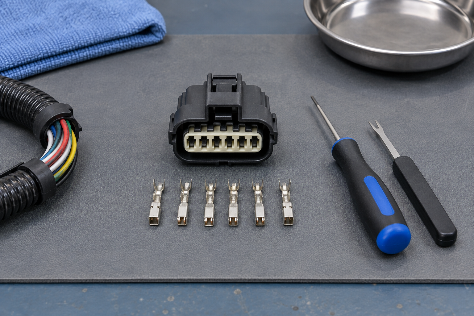
For readers establishing the part identity before inspection, this guide to identifying automotive electrical connectors explains why markings, keying, cavity count, and terminal style should be considered together rather than matched by appearance alone.
How to Transfer Wires Without Mixing the Pinout
Begin with the applicable vehicle wiring diagram, connector view, and service procedure. De-energize the circuit as directed, isolate the energy source, and observe the required wait time before touching the connector. Do not probe energized high-voltage, restraint, braking, steering, or other safety-critical circuits unless the technician is trained, equipped, and explicitly authorized by the relevant service information.
Use a controlled one-cavity-at-a-time process unless the approved procedure says otherwise:
- Record the connector orientation, latch position, cavity numbering, wire colors, tracer colors, wire sizes, seals, and any cavity plugs before release.
- Cross-check that record against the OEM connector view; photographs alone can be mirrored or taken from the mating face instead of the wire side.
- Inspect and, where specified, clean the work area so debris cannot enter the cavities.
- Release the secondary lock with the specified method and position.
- Use the correct extraction tool and release direction for the terminal system; do not pull harder on the wire to overcome an unreleased lance.
- Move one verified terminal to its matching numbered cavity in the new housing, maintaining orientation and seal position.
- Confirm primary retention before proceeding, then seat the secondary lock only after all terminals are correctly positioned.
- Complete an independent cavity-to-circuit verification before reconnecting power.
TE Connectivity and Molex publish insertion and extraction tool resources for their respective component systems. Those resources reinforce a basic process rule: service tools are selected by the terminal and housing system, not by whatever pick or blade happens to fit. General technique is outlined in this guide on how to depin an automotive connector, but the component maker’s instructions and the vehicle procedure remain controlling.
| Observed condition | Likely repair level | Evidence required before proceeding | Stop or escalation trigger |
|---|---|---|---|
| Broken external shell; terminals, seals, and wires appear sound | Housing-only candidate | Exact part/application match, OEM permission, complete cavity map | Any uncertainty in terminal family, keying, seal, or numbering |
| One damaged locking lance or contact interface | Specified terminal replacement, possibly with new housing | Correct terminal, wire range, seal, applicator or service tool, and crimp criteria | Unsupported hand-crimp process or conductor damage beyond the termination |
| Heat or corrosion near multiple cavities | Pigtail or larger harness repair | Extent-of-damage inspection and approved splice or harness procedure | Migration under insulation, widespread resistance heating, or unclear boundary |
| Pinout cannot be confirmed | Pause repair | Vehicle-specific diagram, connector view, and circuit identification | No authoritative mapping or conflicting documentation |
| High-voltage or safety-critical circuit | Authorized specialist procedure | OEM safety steps, qualified personnel, rated equipment, and controlled verification | Any missing training, isolation proof, or application instruction |
Final Checks After Replacing the Connector Housing
Check Terminal Retention and Housing Assembly
Verify that each terminal has reached its specified seated position, the primary retention feature has engaged, seals have not rolled or backed out, and the secondary lock closes without forced pressure. Check the mating latch and connector position assurance feature where fitted. Do not invent a universal pull force: use a manufacturer-specified retention test only when it is part of the approved service process. The distinction between primary and secondary retention is explored further in the guide to female terminal contact retention.
Verify Continuity and Circuit Isolation
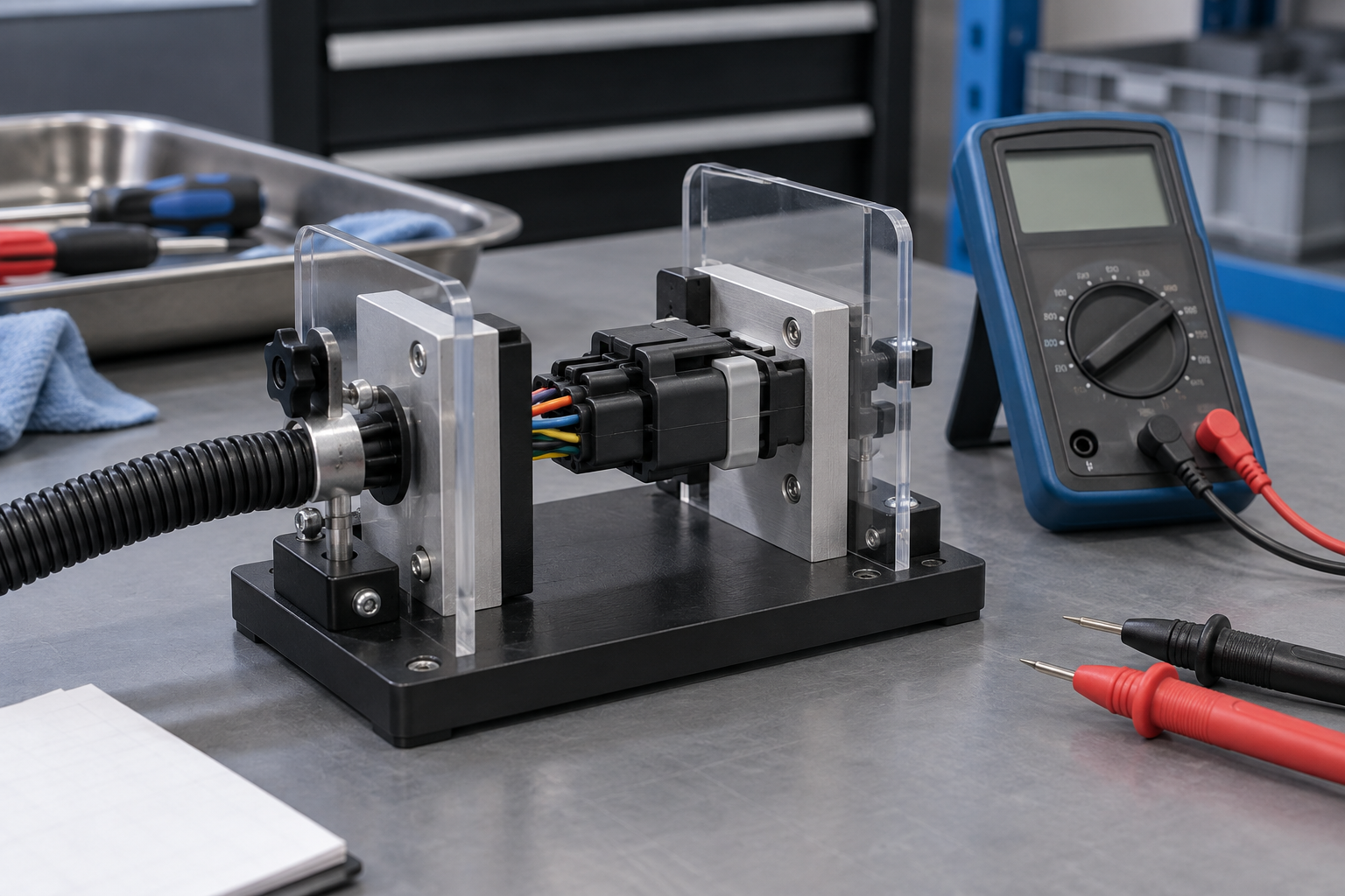
With the circuit in the safe state required by the OEM procedure, verify each repaired path against the correct endpoints and confirm that circuits that must remain isolated are not shorted together or to ground. A continuity tone by itself does not prove terminal contact quality under load, so use any specified resistance, voltage-drop, or functional check with the stated equipment and limits. Never back-probe or energize a protected circuit merely to apply a generic test.
Check Sealing and Final Function
Confirm the interface seal, individual wire seals, unused-cavity plugs, backshell, conduit, and strain relief are correctly positioned. Perform a leak, ingress, or pressure test only when the manufacturer defines the method and acceptance criteria; SAE/USCAR-2 test methods are not blanket permission to improvise a field water test. Finally, reconnect, clear only the fault information the OEM procedure instructs, and perform the prescribed functional verification while watching for heat, intermittency, and strain at the repaired area.
Which Documents Apply to the Repair
Four document layers serve different purposes, and treating them as interchangeable creates avoidable risk:
- SAE/USCAR-2 performance specification: defines laboratory performance expectations and test methods for automotive electrical connector systems. It is not a vehicle repair manual, a universal interchangeability list, or proof that an individual replacement is certified.
- SAE/USCAR-21 crimp performance specification: addresses cable-to-terminal electrical crimp performance. It helps frame validation of a new termination process, but it does not supply the application’s terminal identity, wire range, field tool, or cavity map.
- Component manufacturer application specifications: identify compatible housings, terminals, seals, locks, wire ranges, extraction tools, insertion methods, and assembly controls for a particular product system.
- Vehicle-specific service and wiring documentation: controls connector views, cavity functions, isolation steps, allowable repair scope, splice locations, test limits, and final vehicle checks.
Applicability depends on the destination market, vehicle platform, intended use, and the claims made by the seller or repair provider. Calling a part “USCAR certified” merely because a USCAR test method exists can mislead a buyer. Unsupported interchangeability, sealing, or compliance claims also raise warranty, return, downtime, traceability, and liability exposure. Procurement records should therefore preserve the approved part identity, revision, source documentation, and inspection result.
What to Include in a Replacement-Housing Request
- Freeze the application identity. Capture the vehicle, system, connector maker and series where known, cavity count, keying, latch, terminal family, wire range, seals, and visible markings.
- Define the repair boundary. State whether the request is for a shell, terminals and seals, a service pigtail, or a harness section; an automotive electrical connector repair kit is useful only if every included component and tool matches the approved process.
- Request controlled evidence. Obtain drawings, application specifications, cavity numbering, compatible extraction and insertion tooling, packaging identification, and traceability appropriate to the program.
- Plan validation before release. Assign responsibility for retention, continuity, isolation, sealing, and vehicle-level functional checks, including their acceptance criteria.
- Account for serviceability. Compare technician access, training, tool availability, repair time, and recurrence risk alongside part price.
For teams sourcing configurable automotive wire harness connectors, ZUCH can support a specification-led discussion around connector identification, component configuration, and documentation. Buyers should provide the application evidence and required verification plan rather than asking a supplier to infer fit from a photograph. For broader process context, see this overview of automotive electrical connector repair.
Frequently asked questions
When can I replace only the automotive connector housing?
Replace only the housing when the exact housing, terminal, seal, lock, and cavity configuration are verified; the wires and terminals are undamaged and serviceable; and the OEM procedure allows the transfer. If any identity, pinout, heat, corrosion, retention, or seal question remains unresolved, expand or pause the repair.
When should I replace a connector pigtail instead of the whole harness?
An approved pigtail can be appropriate when damage is confined to the connector end, sound conductor exists at the permitted splice location, and the OEM specifies the splice materials and method. Choose a larger harness repair when heat, corrosion, insulation damage, or conductor degradation extends beyond that controlled boundary.
Can the existing terminals be reused in a new connector housing?
They may be reused only when their identity is compatible and their contact surfaces, spring features, locking lances, crimps, seals, and attached wires meet the application’s inspection criteria. A terminal with reduced contact force, plating damage, overheating, corrosion, or lance deformation should not be made acceptable simply by placing it in a new shell.
What damage means a connector housing should not be reused?
Do not reuse a housing with melted or distorted cavities, broken locks or keying, carbon tracking, damaged seal-support surfaces, contamination that cannot be acceptably removed, or geometry that no longer locates terminals correctly. Follow the component and vehicle documentation for application-specific reject criteria.
How do I transfer wires to a new housing without mixing up the pinout?
Record both connector orientation and cavity numbers, verify them against the OEM connector view, and transfer one wire at a time with the specified extraction tool. Finish with an independent cavity-to-circuit check; wire color alone is not sufficient because colors can repeat, fade, or vary by build.
What tests should be performed after replacing an automotive connector housing?
At minimum, complete the specified terminal-seating and lock checks, circuit continuity and isolation checks, seal and strain-relief inspection, and the OEM functional verification. Perform resistance, voltage-drop, retention-force, or ingress tests only when an authoritative procedure provides the method, equipment, and acceptance limits.
References
- SAE International, USCAR-2-8: Performance Specification for Automotive Electrical Connector Systems.
- SAE International, USCAR-21-4: Performance Specification for Cable-to-Terminal Electrical Crimps.
- TE Connectivity, Extraction Tools.
- Molex, Insertion and Extraction Tools.
Conclusion: replace only what the evidence allows
The decision rule is simple: use a housing-only repair only when exact compatibility, terminal condition, wire condition, cavity mapping, and OEM permission are all confirmed. First identify the connector and circuit; next inspect the housing, terminals, crimps, seals, and adjacent wire; then choose the narrowest approved repair boundary. After transfer, verify terminal seating and retention, circuit continuity and isolation, sealing, strain relief, and the specified vehicle function. Do not treat a continuity tone, matching appearance, or a closed secondary lock as proof that the repair is correct—especially on high-voltage or safety-critical circuits. Good automotive connector repair preserves the harness only when doing so also preserves electrical and mechanical integrity. ZUCH can help buyers review connector configuration and documentation; explore the ZUCH product directory and contact the team with your application details and verified part requirements.