Zhejiang ZUCH Technology Co., Ltd.
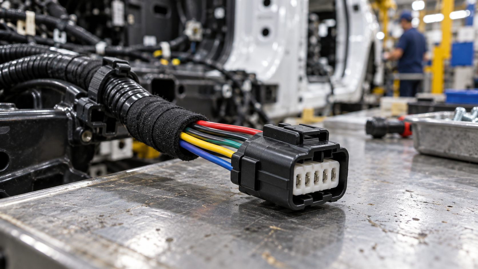
When a procurement engineer in Munich encounters a replacement harness connector with five wires but no reliable part number, the housing may look close to the sample, yet one circuit is a reference return and another is a switched load; a pin-count shortcut could put the wrong terminal or cavity in production. The problem is not solved by finding any five-position plug. A 5-wire automotive connector must be matched to the circuit map, mating interface, terminal and seal system, conductor size, environment, and service process. This guide shows engineering and purchasing teams what to verify before approving a replacement or issuing an RFQ.
Summary: Five wires describe conductors, while five pins describe contact positions; the terms are related but not automatically equivalent. Confirm the wiring diagram, cavity numbering view, mating housing, keying, terminal family, wire range, current and voltage per circuit, sealing, and retention features. ISO 8092 is a relevant road-vehicle harness reference, and SAE USCAR-2 provides a performance framework for automotive electrical connection systems. The next action is to create a five-row circuit matrix and validate a production-intent sample rather than approving a replacement from a photograph.
Is a five-wire connector the same as a five-pin connector?
Not necessarily. A five-wire harness may terminate in five contacts, but it can also include a shield, splice, drain, or an unpopulated cavity; a five-pin housing may carry fewer than five wires. “Wire” describes conductors in the harness, while “pin” usually describes contact positions in a connector interface. The wiring diagram and terminal map settle the difference.
Record the component-side mating part, connector family, key code, cavity count, populated positions, and view orientation. Identify whether the interface is wire-to-wire, wire-to-board, or an integrated sensor or actuator connection. The verified automotive connector identification guide can help structure photos and part-marking notes, but the controlled drawing and vehicle service information remain authoritative.
How should the five circuits be identified before sourcing?
Build a five-row matrix with cavity number, circuit function, wire color and size, terminal part, seal, destination, and test point. Possible functions include supply, ground, reference, signal, communication, or actuator control; these are examples, not a universal pinout. Never infer a circuit solely from wire color or cavity symmetry because harness conventions vary by vehicle, model year, and branch.
Confirm whether the documentation shows the mating face or wire side, then mark cavity 1 and follow the specified numbering direction. For an analog or sensor branch, distinguish signal return from chassis ground when the circuit documentation does so. For a switched load, record inrush and duty cycle as well as nominal current. A five-cavity housing can require mixed terminal sizes, so the RFQ should identify the terminal and crimp method for every populated position.
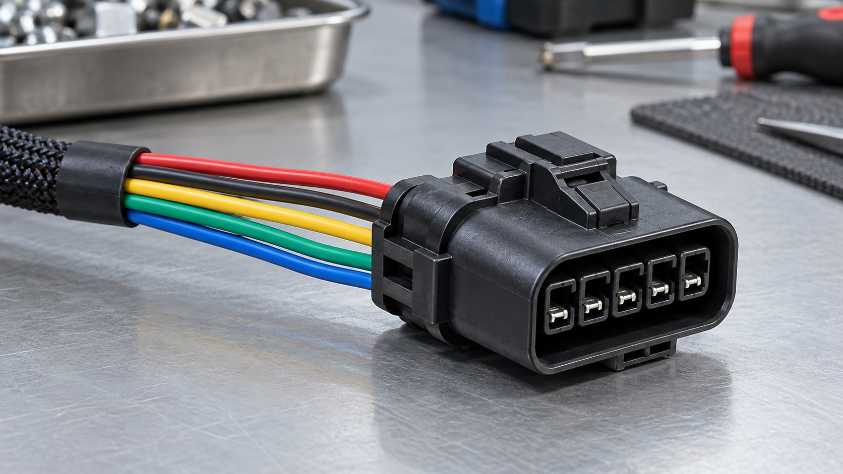
What should be compared when selecting a 5-wire automotive connector?
| Selection dimension | Signal-oriented option | Mixed signal and power option | Evidence to request |
|---|---|---|---|
| Circuit duty | Low-current sensor or communication circuits with controlled noise and reference paths | Different terminals may be needed for supply, return, and control loads | Circuit matrix, current, voltage, duty, and signal definition |
| Terminal and wire | Small terminal and approved conductor range must match crimp tooling | Mixed terminal sizes can optimize each circuit but increase kitting controls | Terminal drawings, wire range, crimp specification, pull-test method |
| Keying and retention | Polarization and secondary lock prevent a small connector from being mis-mated | Higher load or vibration may require stronger retention and visible assurance | Mating drawing, lock details, retention test record |
| Environmental protection | Unsealed design may suit a protected interior location | Sealed design needs wire seals, plugs, and validated assembly process | Exposure profile, seal specification, ingress test plan |
| Service plan | Accessible depinning and terminal replacement can simplify troubleshooting | Repair must preserve cavity map, seal, load path, and lock condition | Service instructions and approved replacement parts |
This comparison describes decision dimensions rather than ranking brands. A supplier’s suitability depends on the exact interface, application limits, and evidence supplied for the proposed configuration.
How do wire gauge, crimp, and seals affect fit?
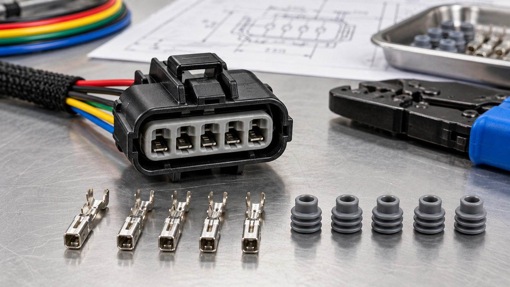
Wire outside diameter determines seal selection, while conductor area determines the terminal’s approved crimp range. A terminal that accepts the conductor may still fail if insulation support, strip length, or seal diameter is wrong. Define conductor area, insulation material and diameter, bend radius, and any splice or strain-relief requirement in the RFQ.
Inspect conductor capture, insulation support, terminal lance engagement, secondary lock, and seal position after assembly. For contact retention concerns, consult ZUCH’s terminal retention guide. For continuity, short-to-ground, insulation resistance, and other harness checks, align the validation plan with the methods described in the wire-harness electrical testing guide. Do not use grease, tape, or a larger terminal as a substitute for the approved interface.
Which RFQ dimensions reveal the real cost of a five-wire assembly?
| Dimension | Buyer should specify | Cost or risk exposed |
|---|---|---|
| Application and location | Cabin, exterior, engine bay, trailer, or industrial vehicle; temperature and fluid exposure | Determines sealing, material, validation, and service controls. |
| Pin and wire map | Five circuit functions, cavity view, wire size, terminal, seal, and destination | Prevents mirrored pinouts, wrong terminals, and rework. |
| Process capability | Manual or automated crimping, tooling, inspection, and operator controls | Changes labor, defect escape, and training requirements. |
| Documentation | Drawings, material declarations, test reports, revision and change-notice practice | Supports audits, change control, and destination-market compliance. |
| Supply continuity | MOQ, lead time, lifecycle status, approved alternates, and packaging | Reduces line stoppage and redesign exposure beyond first purchase. |
Any total-cost estimate should use the buyer’s own labor, scrap, downtime, logistics, and return assumptions. No universal price or savings claim follows from having five wires.
What standards and material evidence apply?
ISO 8092 covers road-vehicle low-voltage wiring-harness connections within its applicable parts. SAE USCAR-2 provides an industry performance specification for automotive electrical connection systems, including system-level electrical and mechanical evaluation. IEC 61984 addresses connector safety requirements and tests within its scope. These references do not replace the vehicle maker’s drawing, customer validation plan, or destination-market regulation.
Request product-specific evidence for any UL/CUL coverage and for PA66 or PA66 GWT material statements. A laboratory accreditation or quality-system certification describes an organization or process scope; it is not automatic proof that every five-wire configuration meets every vehicle requirement. ZUCH states IATF 16949:2016, CNAS laboratory accreditation, and a UL witness laboratory among its capabilities. Buyers should ask for the exact drawing revision, material declaration, test report, and applicable certification scope.
What should a five-wire RFQ include?
- Provide the mating part, connector face and wire-side views, key code, cavity numbering, and mounting envelope.
- List all five circuit functions, voltage, continuous and inrush current, signal type, duty cycle, and spare positions.
- Specify conductor area, insulation diameter, terminal part, plating requirement, seal size, crimp tool, and secondary lock.
- Describe temperature, vibration, fluids, dust, salt, ingress, service access, and expected mating cycles.
- Request sample builds, inspection records, validation methods, revision control, lot traceability, and change-notification terms.
When a buyer writes automotive 5 wire connector in a sourcing request, the phrase should be accompanied by the five-row circuit matrix, mating reference, wire data, and validation scope.
ZUCH manufactures rectangular, RAST, FASTON, terminal, motor, and compressor connector lines. Its connector product directory can support an initial category review; a useful quotation request should still include the complete five-wire circuit matrix and mating-part evidence.
Frequently asked questions
Is a 5-wire connector the same as a 5-pin connector?
No. Five-wire describes conductors in the harness, while five-pin generally describes contact positions. A five-wire harness may include a shield or leave a cavity unused, and a five-pin housing may not have all positions populated. Use the wiring diagram and cavity map to confirm the actual interface.
How do I identify the wires in a 5-wire automotive connector?
Use the vehicle or equipment wiring diagram, identify the documented face view, mark cavity 1, and map each position to circuit function, wire size, terminal, and destination. Confirm color and continuity only as supporting evidence; wire color by itself is not a reliable pinout.
Can I replace a 5-wire connector with another brand?
Only after the complete mating system is shown to be equivalent or requalified. Compare housing geometry, keying, terminal dimensions, wire and seal range, locks, environmental limits, and validation evidence. A shared wire count or similar appearance does not establish interchangeability for a 5 wire car connector.
What should an RFQ include for a 5-wire harness connector?
Include the mating part and drawings, five-row circuit matrix, current and voltage per circuit, conductor and insulation data, terminal and seal references, environment, assembly tooling, tests, annual demand, and change-control expectations. Sample builds should use production-intent wire and crimp processes before volume approval.
References
- ISO 8092, Road vehicles — Connections for on-board electrical wiring harnesses, International Organization for Standardization.
- USCAR-2, Performance Specification for Automotive Electrical Connection Systems, SAE International.
- IEC 61984, Connectors — Safety requirements and tests, International Electrotechnical Commission.
- Vehicle safety resources, National Highway Traffic Safety Administration.
- ZUCH connector product directory and stated quality information.
Conclusion
The dependable 5-wire automotive connector is selected from the circuit map outward. First separate wire count from pin count, then confirm the mating housing, cavity view, keying, terminal geometry, conductor and seal range, locks, and application environment. Build and inspect a sample with production-intent wire and tooling before approving a substitute or releasing an RFQ. ISO 8092, USCAR-2, and IEC 61984 offer useful reference points, but the vehicle maker’s drawing and validation plan determine acceptance. Do not skip retention, continuity, and environmental checks merely because the connector looks similar. ZUCH can help engineering and procurement teams review connector categories through its product directory when the request includes the five-row circuit matrix, mating reference, and required compliance evidence.