Zhejiang ZUCH Technology Co., Ltd.
Illustrative scenario: When Elena, a high-voltage harness engineer in Munich, encountered a tight cabinet corner, she selected an orange right-angle single-conductor connector from an image and released a prototype harness. During the first powered check, the joint showed a rapid temperature rise. The connector was not automatically “bad”; the real failure was approving an interface before the mating geometry, conductor termination, busbar stack, torque process, and thermal test conditions had been defined.
Summary: Treat CT-S/P0136 as supplier-specific series or model naming, not as a standardized interface. Freeze the drawing, mating part, termination process, insulation assumptions, and validation plan before purchase approval. As an illustrative—not product-rated—example, an extra 0.10 mΩ at 200 A dissipates 4 W because P = I²R; small interface losses can therefore consume meaningful thermal margin. The product drawing and a matched, model-specific test report must control every acceptance decision.
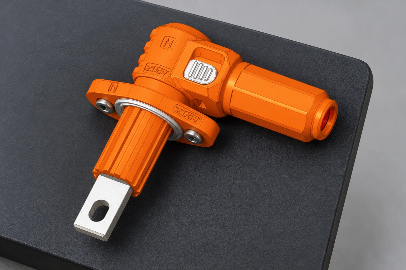
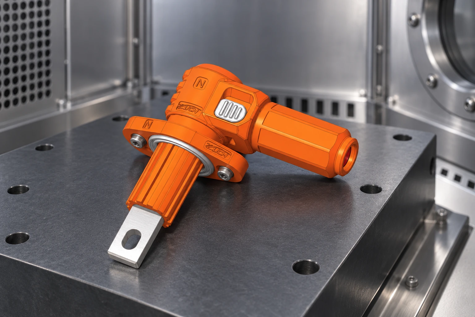
The available image shows an orange right-angle body and an exposed flat lug or tab. It does not establish voltage, current, conductor size, polarity or keying, touch protection, ingress protection, temperature range, materials, or certification. For energy-storage system integrators, harness engineers, and quality teams, a useful specification must convert that visible form into a controlled electrical and mechanical interface.
Define the complete interface before approving the model
Start with an interface control drawing, not a family name
A CT-S/P0136 single-core connector should be released only against a drawing revision that identifies both mating halves and every assembly-critical dimension. The drawing should define the mounting datum, lug or tab dimensions, allowed busbar stack, fastener and washer arrangement, orientation, key or coding features, connector envelope, cable exit direction, and minimum service space. A photograph can support identification, but it cannot be the acceptance document.
Bind the ordered part number to the exact contact, housing, seals, cable accessory, and mate used in validation. Changes to plating, polymer, contact geometry, or termination require change control and a requalification decision.
Use the right-angle package for routing, not as a thermal shortcut
A 90-degree package can reduce cabinet depth and avoid forcing a large cable into a tight bend. The same geometry can make orientation, tool access, assembly sequence, and cable-induced torque more sensitive. The decision therefore belongs in the packaging model and harness drawing, with the intended bend radius and clamp location represented.
| Decision factor | Right-angle package | Straight package | What to verify |
|---|---|---|---|
| Cabinet depth | May reduce axial projection | Usually needs more depth in the cable direction | 3D envelope with mate, boot, cable, and tool space |
| Cable loading | Can redirect the cable early, but may transmit torsion if unclamped | Can simplify axial routing, but may require a larger bend zone | Bend radius, clamp location, side load, and service motion |
| Assembly and maintenance | Orientation and fastener access may be more constrained | Access may be simpler when depth is available | Build sequence, torque-tool access, and removal path |
| Total cost tendency | Can save enclosure volume but increase routing or orientation controls | Can simplify harness handling but consume packaging volume | Installed cost, rework risk, inspection time, and replacement access |
Engineer the conductor-to-contact-to-busbar transition
The current path is a chain: conductor, termination, contacts, exposed tab or lug, fastener stack, and busbar. Specify conductor construction and cross-section, insulation diameter, strip length, termination method, tooling, and process acceptance criteria. Housing fit does not prove termination suitability.
At the busbar end, control flatness, plating compatibility, hole and edge geometry, joint pressure, washer arrangement, tightening method, and any relaxation expected over temperature cycling. A torque value alone is not proof of contact quality; friction, surface condition, stack stiffness, and fastener reuse can change the clamp load. The validation sample should use production-intent cable, tooling, busbar finish, fasteners, and assembly instructions.
Measure the completed path at defined locations and temperatures. IEC 60512-2-1 describes a millivolt-level method for contact resistance across mated contacts. For a high-current assembly, the test plan should state the four-wire measurement points, stabilization condition, sample count, and preconditioning, because a number without the method is not comparable.
Set insulation and touch-protection requirements from the system
Creepage and clearance are application results
Do not copy a spacing value from another connector. Under IEC 60664-1:2020+A1:2025, insulation coordination depends on system variables such as working voltage, impulse conditions, pollution degree, material group, altitude, and the insulation concept. The relevant product or end-equipment standard can add requirements. A practical review should therefore mark each conductive surface in the mated, unmated, and partially assembled states and document the path used for each clearance and creepage measurement. A copper busbar junction box needs an insulation review for its own conductive geometry, not a spacing value borrowed from another interface.
For a focused design explanation, see ZUCH’s guide to energy-storage connector creepage and clearance. The guide can support a checklist, but the controlled drawing and the project’s applicable standards still decide the required distances.
Orange color does not prove touch safety or polarity
Color may assist identification, yet it does not demonstrate finger protection, interlock behavior, polarity control, or safe isolation. The exposed flat tab visible in the image should be treated as a question: is it energized only inside another enclosure, protected by a cover, connected after isolation, or part of a touch-safe mating sequence? Verify the answer through drawings, assembly states, and the final equipment risk assessment. Keying and coding also need a documented misuse check against every connector installed nearby.
Validate the terminated assembly under realistic stress
Qualification should test the production-intent configuration, not a bare connector from the same family. The matrix separates needed evidence from claims that images cannot establish.
| Verification gate | Method and controlled conditions | Evidence to retain | Typical rejection trigger |
|---|---|---|---|
| Contact resistance | Four-wire measurement at defined points before and after conditioning; IEC 60512-2-1 can be considered where applicable | Raw values, setup diagram, instrument details, sample IDs, and limits | Unexplained drift, unstable readings, or a method mismatch |
| Temperature behavior | Production-intent conductor and busbar at stated current, ambient, airflow, orientation, duty cycle, and steady-state criterion; IEC 60512-5-2 is a possible current-temperature method | Temperature map, current trace, ambient record, sample build, and acceptance basis | Limit exceeded at any critical material or joint, or no stable result |
| Retention and handling | Contact retention, cable pull/side load, latch function, and assembly misuse; IEC 60512-15-1 defines a contact-retention method | Load direction, rate, fixture, displacement, damage, and post-test function | Contact movement, latch damage, seal displacement, or loss of continuity |
| Environmental durability | Temperature/humidity sequence plus project-specific vibration, corrosion, fluid, or ingress exposure; IEC 60512-11-1 is one climatic-sequence method | Sequence, severity, powered/unpowered state, interim readings, and final inspection | |
| Production process | Approved tooling, crimp or joining parameters, torque method, traceability, and inspection sampling | Work instruction, calibration, first-article record, and change control | Tooling or material differs from the qualified build |
Test order matters: pristine samples can hide later degradation, while a final value without baseline data cannot show drift. Agree the sequence, limits, sample quantity, and failure-analysis procedure first. For wider context, review this guide to high-current DC connectors.
Match standards to the intended market and use
IEC 61984:2008 states connector safety requirements and tests within its defined scope when no detail specification exists or calls it up. IEC 60512 methods are not, by themselves, product certification. A bridge combination connector also needs part-specific evidence; a generic test method does not certify the assembly.
For North American projects, UL 4128 Edition 6 is an Outline of Investigation for intercell and intertier connectors used in electrochemical battery system applications. UL 1977 Edition 4 covers component connectors for data, signal, control, and power applications. Their applicability depends on the actual connector function, end equipment, installation, ratings, and evaluation path. Do not describe CT-S/P0136 as UL Recognized, Listed, certified, or compliant unless a current model-specific record identifies the exact part and scope.
A procurement checklist for CT-S/P0136
- Obtain the controlled drawing, exact mate, bill of materials, and change-notification terms.
- Confirm cable, termination tooling, busbar stack, fasteners, orientation, and assembly work instructions.
- Document insulation assumptions, touch-protection states, coding, and nearby mismatch risks.
- Approve a model-specific test plan covering resistance, temperature behavior, retention, and environmental exposure.
- Require reports to identify sample part numbers, revisions, build conditions, methods, limits, results, and deviations.
ZUCH can discuss the CT-S/P0136 drawing, mate, customization boundaries, and available verification documents within its energy-storage connector range. Release still depends on evidence matching the system and destination market.
Frequently asked questions
What is a CT-S/P0136 single-core connector?
CT-S/P0136 appears to be supplier-specific model or series naming for a single-conductor connector. It is not enough to define an interoperable interface; use the supplier’s controlled drawing and exact mating-part identification.
Can the current or voltage rating be identified from the image?
No. Housing size, orange color, and a large metal tab do not establish electrical ratings. Request a model-specific datasheet and verify the stated conditions against the terminated assembly and end-equipment design.
Why choose a right-angle single-core connector?
A right-angle form can reduce axial cabinet depth and redirect a cable near the interface. It can also increase sensitivity to orientation, tool access, side load, and cable torque, so verify the full 3D routing and service procedure.
Does an IEC 60512 test report mean the connector is certified?
No. IEC 60512 documents test methods; a report shows only the samples, conditions, method, and results it identifies. Certification or recognition requires a valid scheme and scope that names the relevant model.
What should procurement request before issuing a purchase order?
Request the drawing revision, mating part, material and plating declarations, termination instructions, applicable ratings with conditions, and matched test reports. Also define change notification, incoming inspection, traceability, and the evidence needed for the destination market.
References
- International Electrotechnical Commission, IEC 61984:2008, Connectors — Safety requirements and tests.
- International Electrotechnical Commission, IEC 60512-2-1:2002, Contact resistance — Millivolt level method.
- International Electrotechnical Commission, IEC 60664-1:2020+A1:2025, Insulation coordination for equipment within low-voltage supply systems.
- UL Standards & Engagement, UL 4128 Edition 6, Intercell and Intertier Connectors for Use in Electrochemical Battery System Applications, June 16, 2026.
- UL Standards & Engagement, UL 1977 Edition 4, Component Connectors for Use in Data, Signal, Control and Power Applications, December 7, 2022.
The reliable connector is the one whose interface, process, and evidence all describe the same production assembly.
To review the CT-S/P0136 interface against your conductor, busbar, routing, and validation requirements, contact ZUCH with your controlled application inputs.