Zhejiang ZUCH Technology Co., Ltd.
Illustrative scenario: When Maya, an energy-storage integration engineer in Rotterdam, encountered a hot joint during a cabinet prototype build, she stopped the test and opened the orange insulated interconnect. Discoloration appeared quickly, yet inspection reversed the diagnosis: this was not proof of a “bad box.” The specification had combined adapter, connector and enclosure functions without defining mating geometry, assembly torque or test evidence.
Summary: Treat “CT series copper busbar junction boxes” as a supplier naming phrase, not a complete engineering specification. The pictured part looks like an orange insulated, straight connector-like component, but its internal architecture and ratings are unverified. Freeze the interface drawing first; then validate contact resistance, temperature rise, insulation coordination and misuse controls against the intended assembly. IEC 61984 addresses connector safety requirements and tests, while IEC 60664-1 provides insulation-coordination principles; neither reference by itself proves this product is certified.
For an ESS team, ask what functions the exact part performs in the energized system. The answer must come from its drawing, bill of materials, instructions and scoped reports. Buyers can review ZUCH’s energy-storage connector range, but a category page cannot replace model-specific evidence.
First Resolve the Terminology
Three concepts are often compressed into one label. A busbar junction joins current paths. An adapter or connector provides a defined, potentially separable interface. An enclosure supplies a protective boundary. One product can combine functions, but that must be demonstrated—not inferred from an orange housing or the word “box.”
| Commercial term | Engineering function to verify | Evidence to request | Common specification error |
|---|---|---|---|
| Busbar junction | Carries current across a bolted, spring or other contact interface | Interface drawing, conductor finish, joint-resistance and temperature-rise data | Assuming “copper” defines the contact system, plating and usable current |
| Busbar adapter | Transitions geometry, orientation or mating format | Datum scheme, tolerance stack, allowable movement and mounting method | Checking only nominal dimensions, not misalignment or stack-up |
| Separable connector | Provides repeatable mating and unmating | Mating-cycle procedure, retention, contact-resistance stability and keying | Treating service disconnect capability as automatically safe isolation |
| Enclosure or junction box | Provides a protective boundary around live parts or joints | Access-probe, ingress, flammability and assembly-level evidence as applicable | Inferring an IP class or touch protection from appearance |
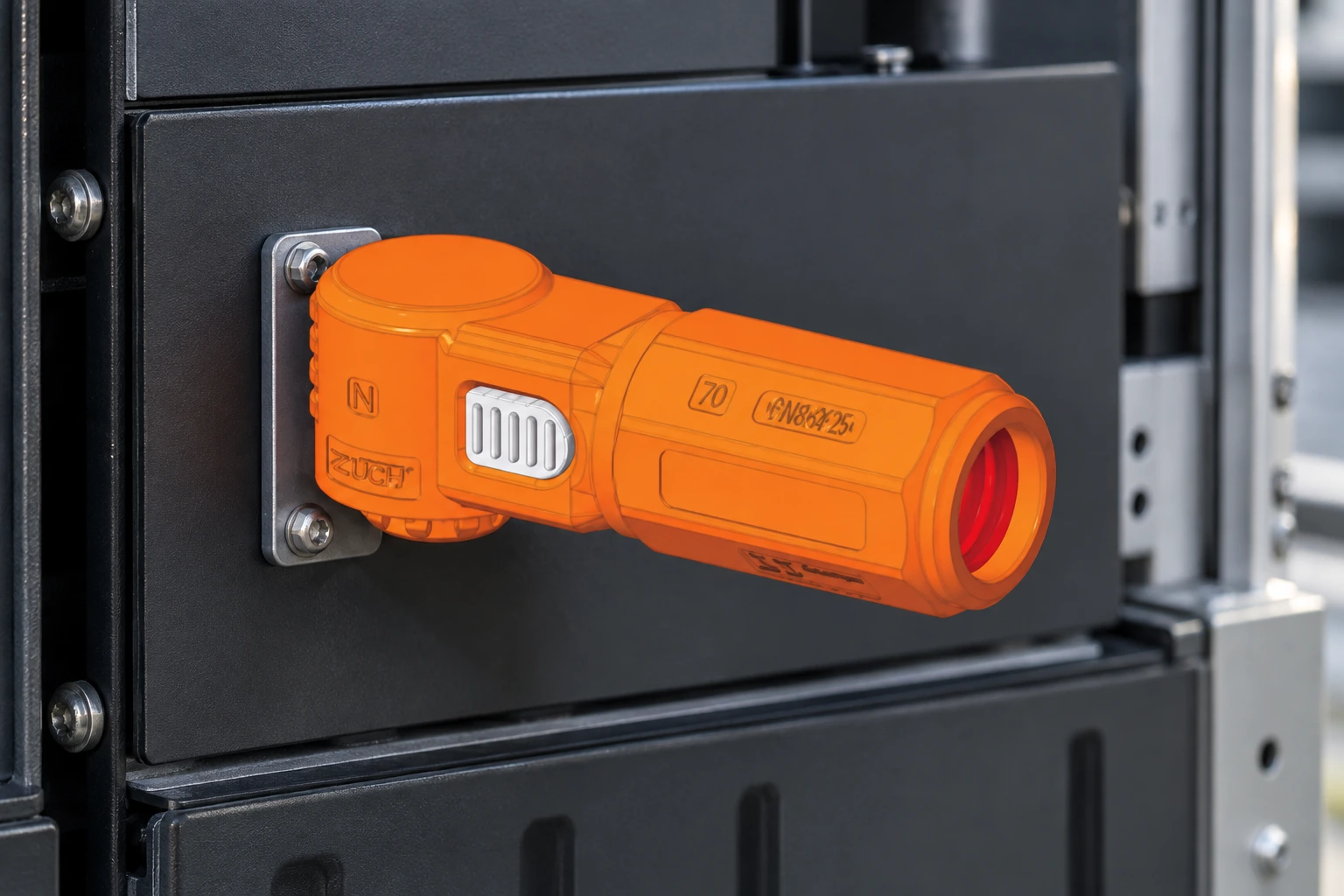
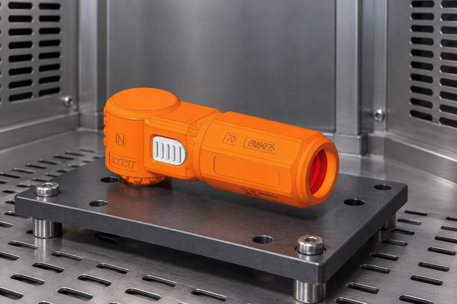
The image shows an insulated straight component with an end opening. It does not establish ratings, conductor size, IP class, touch protection, material, environmental limits or certification. The controlled drawing and exact part number govern.
Use a Mechanical-to-Electrical Interface Workflow
1. Freeze the system boundary and mechanical datums
Define whether the device sits between cell, module, rack, power-conversion equipment or a service harness. Record mating parts, busbar thickness and flatness, terminal geometry, orientation, mounting constraints, cable loads and assembly sequence. Combined tolerances, thermal expansion and harness forces can load a nominally matching contact unevenly. When the layout includes a bridge combination connector, document that interface and its mating parts separately.
2. Control contact pressure, torque and joint resistance
A bolted joint needs a supplier-defined fastener, washer stack, surface condition, tightening method and torque window. A plug contact needs correct geometry and retention. Never infer torque from fastener diameter alone: friction, plating and joint construction change contact pressure.
Measure initial and post-conditioning contact resistance with a defined fixture and measurement points. IEC 60512-2-1 describes millivolt-level contact-resistance testing. A result including busbar, cable or fixture resistance cannot be compared fairly with a contact-only value. See ZUCH’s guide to high-current DC connector design.
3. Verify the thermal path in the final assembly
Joule heating follows P = I²R; rising joint resistance therefore matters more as current increases. This is a design relationship, not a rating. Test the intended duty cycle with enclosure, heat sources, ventilation, conductor heat sinking, orientation and maximum ambient represented. Measure the contact region and material-critical locations, not only the outer shell.
An undocumented interface can cause thermal alarms, teardown and supplier disputes. Higher unit cost may still reduce total cost when it buys controlled drawings, instructions, traceability and useful qualification evidence.
Design Insulation, Isolation and Error-Proofing as a System
IEC 60664-1 treats insulation coordination through factors such as system voltage, overvoltage category, pollution degree, material group, clearances and creepage distances. A photo cannot answer those inputs. Map conductive parts in normal, partially mated, unmated and fault-relevant states; then assess the completed installation. ZUCH’s explanation of creepage and clearance for energy-storage connectors provides useful background, but the project’s applicable product and system standards still control. The geometry of a CT-S/P0136 single-core connector must likewise be checked against its own drawing.
Service isolation is an architecture, not an orange cover. Define what interrupts load current, provides verifiable isolation, discharges stored energy and prevents reconnection. If the component is not load-breaking, procedures and interlocks must prevent disconnection under load. Assess touch protection in all states, including with a mating half removed.
Error-proofing should address polarity, orientation, incomplete mating and wrong-variant insertion through keying, positive latch indication and durable identification. Color is only a secondary cue.
| Design gate | Question to close | Suggested verification | Release evidence |
|---|---|---|---|
| Geometry | Do all tolerances mate without harmful side load? | Worst-case tolerance review and representative fit check | Controlled 2D/3D interface drawing |
| Electrical joint | Is resistance stable after assembly and conditioning? | Defined millivolt-level resistance method before and after relevant conditioning | Test setup, measurement points and results |
| Thermal | Does the complete installation remain within every component limit? | Temperature-rise test using project duty cycle and enclosure conditions | Thermocouple map, loads, ambient and pass criteria |
| Insulation | Are clearance, creepage and dielectric properties suitable? | Insulation-coordination review plus applicable dielectric tests | Voltage assumptions, pollution degree, materials and report scope |
| Service safety | Can personnel isolate, verify and access the system safely? | Hazard review, access-probe checks and service-sequence validation | Instructions, interlock logic and residual-risk record |
| Misuse | Can a wrong or partial connection occur? | Variant challenge test and incomplete-mating assessment | Keying matrix and inspection criteria |
Standards and Test Scope: Match the Product Architecture
- IEC 61984 covers safety requirements and tests for connectors. It may be relevant if the CT component is in fact a connector within its scope. Referencing the standard is not evidence that an unnamed part was tested or certified.
- IEC 60512 series provides test and measurement methods for connectors; IEC 60512-2-1 addresses contact resistance at millivolt level. A method result is meaningful only with the specimen, conditioning, fixture and acceptance criteria identified.
- IEC 60664-1 provides insulation-coordination principles for equipment within low-voltage supply systems. It informs creepage and clearance decisions but does not confer a product approval.
- IEC 61439 series concerns low-voltage switchgear and controlgear assemblies. Use it only when the busbar connection is part of an assembly within the applicable part’s scope; it should not be presented as a standalone connector certification.
- UL 1977 may be considered for component connectors in North American equipment, subject to its scope and end-use conditions. UL 4128 concerns intercell and intertier connectors for use in electrochemical battery system applications; relevance depends on the actual architecture. Neither designation should be attached to this CT series without a verifiable listing or recognition record for the exact model.
Procurement should request the issuer, exact model, standard edition, tested configurations, conditions, result, issue date and conditions of acceptability. A logo or report for a neighboring model does not close the evidence chain.
A Practical RFQ and Qualification Checklist
- Name the function: state whether the requirement is a permanent junction, geometry adapter, separable connector, protective enclosure or a documented combination.
- Attach the interface control drawing: include mating parts, datums, tolerance stack, assembly access and anti-rotation or strain-management details.
- Define operating conditions: provide system voltage, realistic current duty cycle, ambient and enclosure conditions, fault assumptions, contamination, vibration and service frequency—without turning provisional values into product claims.
- Specify evidence: request resistance and temperature-rise protocols, insulation basis, relevant environmental/mechanical conditioning, traceability and change-control expectations.
- Approve in the end assembly: use samples from the intended configuration and repeat critical checks after the conditioning that reflects the application.
For battery racks and adjacent power hardware, ZUCH can discuss configurable connection interfaces within a broader energy-system connection solution. The disciplined approach is to begin with drawings and required evidence, then decide whether the proposed CT series configuration matches the application.
Frequently Asked Questions
What are CT series copper busbar junction boxes?
The phrase appears to be a supplier or product-family label, not a universal technical classification. Confirm from the exact drawing whether the item is a busbar junction, adapter, separable connector, enclosure or combined assembly.
Can I determine the current rating from busbar size or the product photo?
No. Current capability depends on the complete contact system, materials, resistance, thermal path, duty cycle, ambient conditions and enclosure. Request model-specific rating conditions and validate temperature rise in the intended installation.
How should torque be specified for a copper busbar connection?
Use the supplier-approved joint stack, surface condition, tightening tool and torque procedure for that exact interface. Do not copy a value from a similar fastener because friction and contact construction can produce different clamp force.
Does an insulated orange housing provide touch protection?
Appearance alone does not prove it. Evaluate access to live parts in mated, partially mated, unmated and service states using the applicable product or assembly requirements.
Which standard applies: IEC 61984, IEC 61439, UL 1977 or UL 4128?
That depends on product architecture, end use and destination market. IEC 61984 and UL 1977 may be relevant to connectors; IEC 61439 applies only in the proper low-voltage assembly context; UL 4128 is specific to intercell/intertier connectors for electrochemical battery systems. Ask a qualified compliance reviewer to confirm the applicable scope and edition.
References
- International Electrotechnical Commission, IEC 61984, Connectors — Safety requirements and tests, IEC Webstore catalogue.
- International Electrotechnical Commission, IEC 60512-2-1, Connectors for electronic equipment — Tests and measurements — Electrical continuity and contact resistance tests, IEC Webstore catalogue.
- International Electrotechnical Commission, IEC 60664-1, Insulation coordination for equipment within low-voltage supply systems — Part 1: Principles, requirements and tests, IEC Webstore catalogue.
- International Electrotechnical Commission, IEC 61439 series, Low-voltage switchgear and controlgear assemblies, IEC Webstore catalogue.
- UL Standards & Engagement, UL 1977, Component Connectors for Use in Data, Signal, Control and Power Applications; and UL 4128, Intercell and Intertier Connectors for Use in Electrochemical Battery System Applications, official standards catalogue.
The durable rule is simple: qualify the interface and the assembled system, not the product-family name or the housing color.
To review a CT series proposal, send ZUCH the mating drawing, duty cycle, installation conditions and required test scope through the contact team. The response can then focus on documented fit, testability and application limits rather than an unsupported catalogue match.