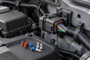
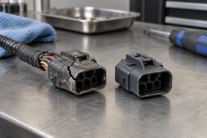
Positive Locking Terminals: Where Secondary Retention Is Essential
Positive locking describes a terminal or connector system that uses a defined mechanical feature to resist unintended disengagement or contact movement. Use the controlled terminal, mating component, housing, and application requirements before making a sourcing or release decision.
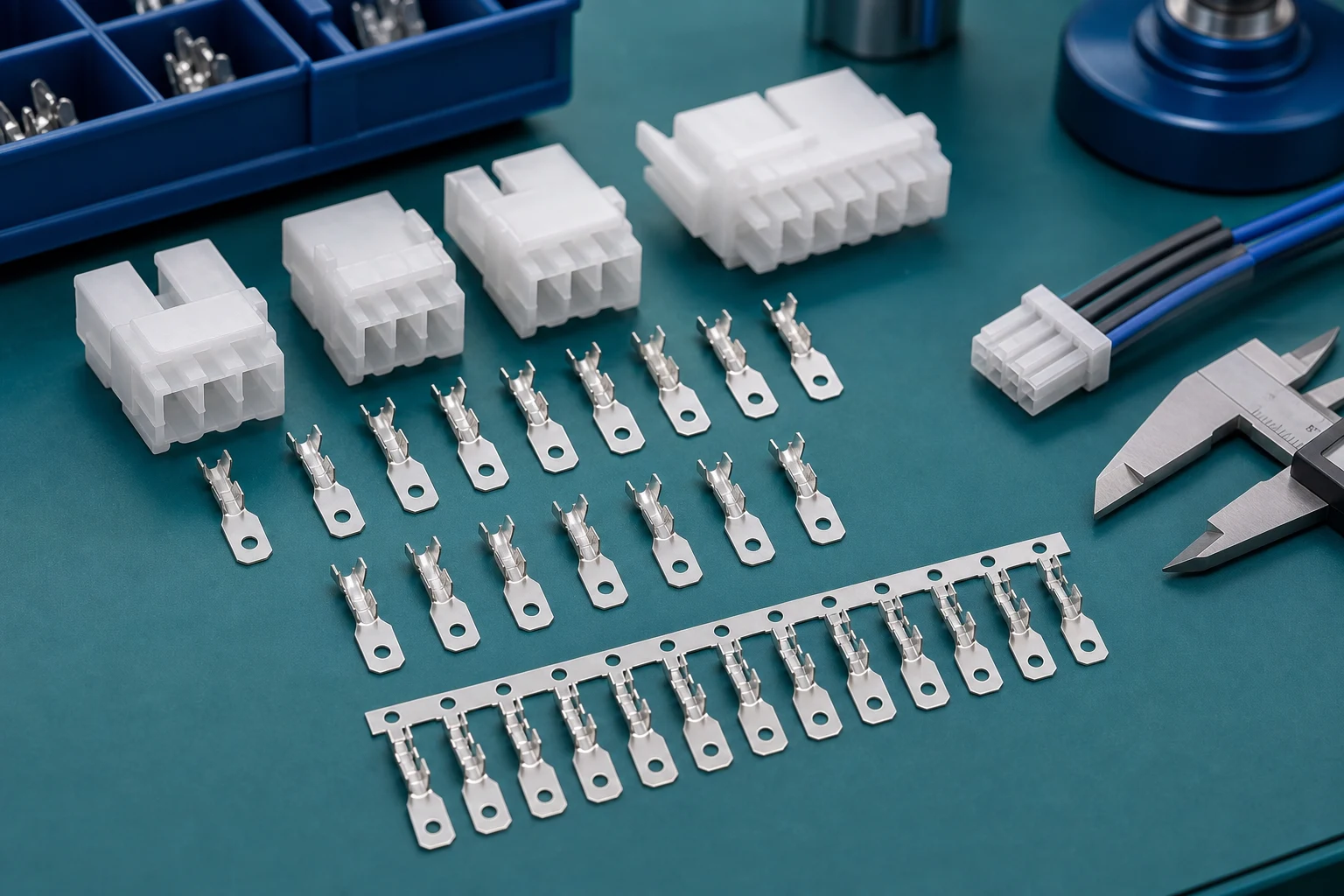
Contents
Part 1. What does positive locking mean in a terminal system?
Positive locking describes a terminal or connector system that uses a defined mechanical feature to resist unintended disengagement or contact movement. The exact mechanism varies by component family. Specify the contact, mating terminal, housing, and lock feature together instead of assuming that the phrase alone defines a complete application solution.
| Locking layer |
Buyer question |
Why it matters |
| Mating interface |
Does the tab-to-receptacle or plug-to-header lock address separation only? |
Interface locks do not automatically retain the contact inside the housing |
| Contact position |
Which primary feature retains the terminal in the cavity? |
Positive locking terminology must map to the actual retention feature |
| Assurance feature |
Is a secondary lock or position assurance device required by the connector system? |
Secondary devices confirm state; they are not interchangeable across families |
Part 2. Which retention layers should be separated?
Separate interface retention from contact-to-housing retention. A tab-to-receptacle lock may address mating separation, while a contact lance and a secondary device address contact position inside a housing.
Each layer has a distinct purpose, inspection condition, and possible failure mode.
Part 3. Where does secondary retention add value?
Secondary retention may be needed where the selected connector system calls for an additional position-assurance or locking feature after primary contact engagement. It can help control assembly state and reduce the risk of an unseated contact remaining unnoticed. Its use must follow the specified connector architecture, rather than being inferred from a general positive-lock term.
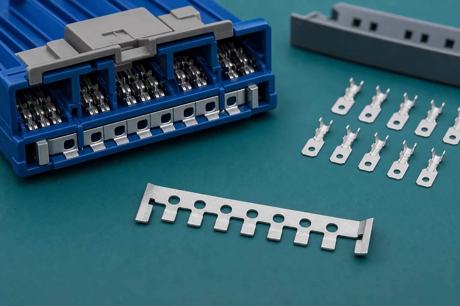
Part 4. How do vibration and wire dress affect the decision?
Movement, bundle mass, tight routing, and repeated handling can load the terminal system in ways that are not visible in a static drawing review. Define the wire exit, support points, service movement, housing constraints, and environmental conditions so that the chosen retention approach is evaluated in the actual installation envelope. For a related selection reference, see Female Terminal Contact Retention: Causes of Back-Out and How to Prevent It.
| RFQ field for locking |
Minimum detail |
Why sourcing needs it |
| Lock architecture |
Primary feature, secondary device, and housing family |
Prevents “positive lock” language without a defined mechanism |
| Assembly order |
Insertion, primary verification, secondary install stage |
Wrong sequence can hide an unseated contact |
| Dynamic loads |
Vibration, service movement, bundle mass, routing |
Shows whether the lock is reviewed in the real envelope |
| Inspection |
Visual, positional, or process check plus records |
Gives SQE a repeatable acceptance method |
Part 5. What should the assembly sequence control?
The work instruction should identify terminal orientation, insertion confirmation, primary-lock verification, secondary-lock position where applicable, and the reaction plan for a rejected contact. A secondary device should be installed only at the correct stage for the selected system; forcing it before contacts are seated can conceal an assembly error.
Important: Positive-lock terminology describes a mechanical intent, not programme approval — use the controlled connector drawing, work instruction, and acceptance plan before releasing production (Molex family documentation context).
Part 6. What belongs in a release and RFQ package?
Include the controlled terminal and housing references, mating interface, conductor definition, lock features, operating conditions, assembly sequence, inspections, samples, and acceptance evidence. This gives engineers and buyers a common basis for evaluating a component route without representing the route as a finished-system approval.
Part 7. Which ZUCH route supports component discovery?
Use ZUCH’s Connecting Terminals hub and the products catalogue to identify terminal families that may include positive-lock or secondary-retention options. Treat the pages as a discovery starting point, then confirm the exact lock feature on controlled drawings and samples.
RFQ inputs
- Terminal, mate, housing, and named primary/secondary lock features.
- Drawing revision, conductor definition, crimp specification, and cavity orientation.
- Vibration, routing, service access, and environmental constraints.
- Assembly sequence, inspection checkpoints, sample quantity, and acceptance records.
- Change-control rules when a lock feature or housing revision changes.
Fit Boundary
This guide compares retention layers and secondary-lock use cases for connecting terminals. It does not certify a finished harness, automotive release, or field rework without programme evidence. Send controlled inquiries through ZUCH’s apply-sample page or contact route. For a related technical topic, see About Rectangular Automotive Connectors.
FAQ
What is a positive locking terminal?
It is part of a connection system with a specified mechanical feature intended to resist unintended disengagement. The complete retention strategy depends on the matched components.
Is secondary retention always required?
No. Use it when the selected connector system and controlled application require it; it is not a generic replacement for primary contact retention.
What is the difference between a primary and secondary lock?
A primary feature normally retains the contact or mating interface first. A secondary feature adds the defined assurance or reinforcement specified by the connector system.
Can a positive lock prevent terminal back-out?
Only when the relevant feature addresses contact-to-housing retention and is correctly matched, inserted, and verified. Interface locks and contact locks are not automatically the same.
Why is wire dress important?
Wire routing and bundle loads can transfer force to the contact or housing, so the retention system must be reviewed in its actual installation envelope.
How should secondary locks be inspected?
Use the specified visual, positional, or process check for the actual connector family and record the programme-defined response to any mismatch.
What should I include in an RFQ?
Include terminal, mate, housing, lock details, wire and environment, assembly sequence, inspection method, sample needs, acceptance criteria, and change control.
References
 Zhejiang ZUCH Technology Co., Ltd.